MODBUS TCP

Hello again,

I'm encountering an issue with another device from the same series. This particular device features analog input and output, each with four channels. The analog output is of the Read/Write type, operating with a function code of 03. It's designed to output either voltage (ranging from +/- 0.06 to +/- 10V) or current (4-20mA).

My objective is to output a voltage of 2V using the Write Holding Register function. I've implemented the corresponding code, which I'm providing below. However, upon measuring the voltage at the output terminals, it doesn't match the intended 2V.

Could anyone provide assistance in resolving this discrepancy?
Code:
#include <SPI.h>
#include <Ethernet.h>
#include <ArduinoRS485.h>
#include <ArduinoModbus.h>

byte mac[] = {0xDE, 0xAD, 0xBE, 0xEF, 0xFE, 0xED};
IPAddress ip(172, 18, 7, 161);
EthernetClient ethClient;
ModbusTCPClient modbusTCPClient(ethClient);

IPAddress server(172, 18, 7, 159);

int MB_HR[4]; // Array to hold int values for holding registers

void setup() {
  Serial.begin(9600);
  Ethernet.init(29);

  while (!Serial) {
    ;
  }

  Ethernet.begin(mac, ip);

  if (Ethernet.hardwareStatus() == EthernetNoHardware) {
    Serial.println("Ethernet shield was not found. Sorry, can't run without hardware. :(");
    while (true) {
      delay(1);
    }
  }

  if (Ethernet.linkStatus() == LinkOFF) {
    Serial.println("Ethernet cable is not connected.");
  }
}

void loop() {
  if (!modbusTCPClient.connected()) {
    Serial.println("Attempting to connect to Modbus TCP server");

    if (!modbusTCPClient.begin(server, 502)) {
      Serial.println("Modbus TCP Client failed to connect!");
    } else {
      Serial.println("Modbus TCP Client connected");
    }
  } else {
    Serial.println("Attempting to read A-I/O status from server");
 
    updateholdingregisters();
  }
}

void updateholdingregisters() {
  Serial.println("Analog Output status");

  for (int i = 0; i < 4; i++) {
    int valueToWrite = 1000;
    MB_HR[i] = valueToWrite;
 
    boolean writeSuccess = modbusTCPClient.holdingRegisterWrite(0x01, i, MB_HR[i]);
 
    if (writeSuccess) {
      Serial.print("Wrote to AO ");
      Serial.print(i);
      Serial.println(": Write successful");
    } else {
      Serial.print("Failed to write to AO ");
      Serial.println(i);
    }

    int readValue = modbusTCPClient.holdingRegisterRead(0x01, i);
 
    if (readValue != -1) {
      Serial.print("Read from AO ");
      Serial.print(i);
      Serial.print(": ");
      Serial.println(readValue);
    } else {
      Serial.print("Failed to read from AO ");
      Serial.println(i);
    }
  }

  delay(1000); // Adjust delay as needed
}

serial output
Code:
Attempting to connect to Modbus TCP server

Modbus TCP Client connected

Attempting to read A-I/O status from server

Analog Output status

Wrote to AO 0: Write successful

Read from AO 0: 2000

Wrote to AO 1: Write successful

Read from AO 1: 2000

Wrote to AO 2: Write successful

Read from AO 2: 2000

Wrote to AO 3: Write successful

Read from AO 3: 2000


device settings
1711621524174.png
 
That's interesting, you are writing value 1000 to AOx but you are reading back value 2000 from AOx.

You may want to try the other use of the modbusTCPClient.holdingRegisterWrite() command.
Instead of boolean writeSuccess = modbusTCPClient.holdingRegisterWrite(0x01, i, MB_HR[i]);
try boolean writeSuccess = modbusTCPClient.holdingRegisterWrite(i, MB_HR[i]);

The same applies to reading the AOx register: try int readValue = modbusTCPClient.holdingRegisterRead(i); instead of
int readValue = modbusTCPClient.holdingRegisterRead(0x01, i);

Paul
 
Hi Paul,

Thanks for your reply. I implemented your suggestion, but now the code is unable to write into holding register.

code I used:


Code:
#include <SPI.h>
#include <Ethernet.h>
#include <ArduinoRS485.h>
#include <ArduinoModbus.h>

byte mac[] = {0xDE, 0xAD, 0xBE, 0xEF, 0xFE, 0xED};
IPAddress ip(172, 18, 7, 161);
EthernetClient ethClient;
ModbusTCPClient modbusTCPClient(ethClient);

IPAddress server(172, 18, 7, 159);

int MB_HR[4]; // Array to hold int values for holding registers

void setup() {
  Serial.begin(9600);
  Ethernet.init(29);

  while (!Serial) {
    ;
  }

  Ethernet.begin(mac, ip);

  if (Ethernet.hardwareStatus() == EthernetNoHardware) {
    Serial.println("Ethernet shield was not found. Sorry, can't run without hardware. :(");
    while (true) {
      delay(1);
    }
  }

  if (Ethernet.linkStatus() == LinkOFF) {
    Serial.println("Ethernet cable is not connected.");
  }
}

void loop() {
  if (!modbusTCPClient.connected()) {
    Serial.println("Attempting to connect to Modbus TCP server");

    if (!modbusTCPClient.begin(server, 502)) {
      Serial.println("Modbus TCP Client failed to connect!");
    } else {
      Serial.println("Modbus TCP Client connected");
    }
  } else {
    Serial.println("Attempting to read A-I/O status from server");
 
    updateholdingregisters();
  }
}

void updateholdingregisters() {
  Serial.println("Analog Output status");

  for (int i = 0; i < 4; i++) {
    int valueToWrite = 1000;
    MB_HR[i] = valueToWrite;
 
    boolean writeSuccess = modbusTCPClient.holdingRegisterWrite(i, MB_HR[i]);
 
    if (writeSuccess) {
      Serial.print("Wrote to AO ");
      Serial.print(i);
      Serial.println(": Write successful");
    } else {
      Serial.print("Failed to write to AO ");
      Serial.println(i);
    }

    int readValue = modbusTCPClient.holdingRegisterRead(i);
 
    if (readValue != -1) {
      Serial.print("Read from AO ");
      Serial.print(i);
      Serial.print(": ");
      Serial.println(readValue);
    } else {
      Serial.print("Failed to read from AO ");
      Serial.println(i);
    }
  }

  delay(1000); // Adjust delay as needed
}

Serial output

Code:
Attempting to connect to Modbus TCP server

Modbus TCP Client failed to connect!

Attempting to connect to Modbus TCP server

Modbus TCP Client connected

Attempting to read A-I/O status from server

Analog Output status

Failed to write to AO 0

Failed to read from AO 0
 
I implemented your suggestion, but now the code is unable to write into holding register.
OK, so that's not going to work. Back to the previous code.

Are you actually using this product: IO5202 with 4 AI/AO?

Another question on your message #24. You stated:
However, upon measuring the voltage at the output terminals, it doesn't match the intended 2V.
What did you actually measure?

Paul
 
Yes, Please refer the post #26, I attached device settings
Did you check the sub-settings as well? See the manual, paragraph 5.7.4 Analog Output (AO) and 5.7.4.1 AO Detail Settings.

I have set the output type to be voltage, so I tried measuring voltage across AO0+ and AO0-
OK, but what voltage did you actually measure then? You said "it doesn't match the intended 2V" so I'm curious what voltage you saw.

Paul
 
I sorted the issue with analog output. I was providing incorrect values, which resulted in improper output voltage measurements. However, I've encountered another problem with reading analog input. I have a PT100 temperature transmitter that outputs 4-20mA. I've connected it as an input to one of the analog input channels(AI3). Upon measuring the current value with a multimeter, it showed 4.7mA for temperature. The device is supposed to read the current in terms of μA, which should be 4700. However, it's consistently reading values as 0. I'm attaching the code I used for reference.
Code:
#include <SPI.h>
#include <Ethernet.h>
#include <ArduinoRS485.h>
#include <ArduinoModbus.h>

byte mac[] = {0xDE, 0xAD, 0xBE, 0xEF, 0xFE, 0xED};
IPAddress ip(172, 18, 7, 161); // Teensy ethernet shield IP (static IP)
EthernetClient ethClient;
ModbusTCPClient modbusTCPClient(ethClient);

IPAddress server(172, 18, 7, 159); // Atop IP address (static IP)

boolean MB_IR[4];

void setup() {
  Serial.begin(9600);
  Ethernet.init(29);

  while (!Serial) {
    ;
  }

  Ethernet.begin(mac, ip);

  if (Ethernet.hardwareStatus() == EthernetNoHardware) {
    Serial.println("Ethernet shield was not found. Sorry, can't run without hardware. :(");
    while (true) {
      delay(1);
    }
  }

  if (Ethernet.linkStatus() == LinkOFF) {
    Serial.println("Ethernet cable is not connected.");
  }
}

void loop() {
  if (!modbusTCPClient.connected()) {
    Serial.println("Attempting to connect to Modbus TCP server");
    connectToModbusServer();
  } else {
    Serial.println("Attempting to read registers from server");
    updateInputRegisters();
  }
}

void connectToModbusServer() {
  if (!modbusTCPClient.begin(server, 502)) {
    Serial.println("Modbus TCP Client failed to connect!");
  } else {
    Serial.println("Modbus TCP Client connected");
  }
}

void updateInputRegisters() {
  Serial.println("Register status");
 
  // Read input registers
  Serial.println("Analog Input status");
  for (int i = 0; i < 4; i++) {
    int inputStatus = modbusTCPClient.inputRegisterRead(0x01, i);

    if (inputStatus != -1) {
      Serial.print("Read from AI ");
      Serial.print(i);
      Serial.print(": ");
      Serial.println(inputStatus);
    } else {
      Serial.print("Failed to read from AI ");
      Serial.println(i);
    }
  }

  delay(1000); // Adjust delay as needed
}

serial output

Code:
Attempting to read registers from server

Register status

Analog Input status

Read from AI 0: 0

Read from AI 1: 0

Read from AI 2: 0

Read from AI 3: 0

Attempting to read registers from server

Register status

Analog Input status

Read from AI 0: 0

Read from AI 1: 0

Read from AI 2: 0

Read from AI 3: 0
 
This is a bare PT100 “Resistance Temperature Detector”. It's basically a resistor so it does not output a current.
You can not hook up such a resistor to a 4-20mA current loop.
Whatever circuit you will be using to measure the resistance [and thus the temperature], there is a general rule that the current through a PT100 should never exceed 1mA to avoid self-heating.
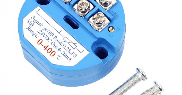
If you want to use the 4-20mA current loop for temperature measurement, purchase a device like this.

Paul
 
This is a bare PT100 “Resistance Temperature Detector”. It's basically a resistor so it does not output a current.
You can not hook up such a resistor to a 4-20mA current loop.
Whatever circuit you will be using to measure the resistance [and thus the temperature], there is a general rule that the current through a PT100 should never exceed 1mA to avoid self-heating.
If you want to use the 4-20mA current loop for temperature measurement, purchase a device like this.
Hi Paul,

Thanks for the information. I was not aware of this. The PT100 sensor is connected to this transmitter

The output of this transmitter is connected to one of the analog input of the device
 
I suppose you are trying to read out these registers?
1712258201143.png

Not sure whether I can be of any help here. I think you just have to fiddle with the settings until you read something that looks valid.

Paul
 
Back
Top