USB connection from D+ / D- pins with external supply

nitrojam

Member
Hello,

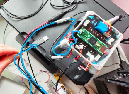
I am running a Teensy 4.1 inside a box, and it is powered from a PSU (picoPSU for those who know it) on 5V.

I have a custom USB cable (with 5V disconnected) which I connect from the Teensy USB port tto my PC in order to program the Teensy (still powered by the Pico PSU and not the USB port) : everything is working fine with Arduino / TeensyDuino.

However, I want to be able to not use the Teensy USB port, but the D+ / D- pins (just below the Usb Connector) : I therefore connect D+ and D- and GND to a USB cable but when plugged to the PC, nothing happened. If I switch D+ and D-, I got a Code 43 error.

Would you have any idea of why it does work with my custom USB cable from the Teensy usb Connector but not from a USB cable connected to the D+ / D- and GND pins ?

Thanks alot !

PS : I'm running Windows 10 if that matters !
 
Would you have any idea of why it does work with my custom USB cable from the Teensy usb Connector but not from a USB cable connected to the D+ / D- and GND pins ?

This really should work.

Any chance the wire colors aren't matched up to the corresponding pins inside the cable? (for example, white and green really connected to GND and +5V)
 
Thanks for your feeback!
I did check with my multi meter that the D+ / D- and ground cables are connected to the right pin on the USB connector so no, it seems to be well wired !

ok so it is really strange ... humm the only difference would be that the cable that works is 2 smaller in length than the on connected directly to D+ / D- (this one is 1.5m / 2m). But even 2m should not be too long ?
 
I could not tell from your description, if there is a common GND signal? That is does your USB GND connect to the Teensy?

Edit: sounds like there is, but would double check... (I was thinking of a different thread....)

But Pictures of your setup might help. For example, to show you are using the right connections:
1714220836229.png

That is you are using the little tiny pads under the USB connector, not the 5 pin connector pins that are
for USB Host.
 
Last edited:
Thanks for the feedback : I do use indeed the D- / D+ you mention (the ground is the common ground). I also check with my multimeter that the small pins from the usb connector are indeed connected to my USB cable so evrything seems to be ok ... I really don't understand why it doens't work !
 
Is the GND pin inside the USB connector on the cable (the end that connects to the PC) also connected to the shielding / metal shell of the connector?
 
no the shield is not connected to any ground : might be the issue ?
Might be - seems there was a recent other post where that was the issue.

Started that reply and deleted when p#1 appeared as wasn't sure of the 'recent post' covering that issue.
If the shield on that cable was connected to the removed plug it is part the GND to the host it seems.
 
If you don't find the solution, try taking some photos so we can actually see.

Might help, might not. Worst case you waste just a few minutes to shoot photos and transfer (maybe resize) so they can be posted here.

Many times on this forum a problem has turned to be a misunderstanding where words communicated the correct thing, but then when we see a photo the problem turns out to be a misunderstanding about what those words really mean. Usually a photo clears these things up very quickly.
 
Thanks all for your feedback : I did test with the shield connected to GND but it doesn't change anything.

Then I check the continuity from GND / D+ and D- from the usb connector connected to the D+ / D- pins and the usb connector connected to the Micro usb from the teensy and there is continuity so D+, D- and GND are indeed all well connected ...

The D+ / D- and GND pins go through a PCB and some connectors before reaching the USB connector in the PC : everything seems to work but to be sure, I connect the Teensy directly to usb cable and it WORKS !
The issue must come from the way between the teensy and the USB connector : I'll continue the investigation.

Thanks for your help, I'll let you know if I found something useful !
 
I don't think D+ & D- are related to the ground,they must be differential inputs to avoid noises,due to the
cable length,look at that:

 
You right, but it still need a ground for reference
https://electronics.stackexchange.c...ive-affects-of-not-grounding-a-usb-connection

Just redo all the wiring and still not working ... the D+ and D- are connected to a PCB with a jst connector then it is out with a jst connector to lemo connector style in a cable and this cable then go to another lemo connector which is connected to the cable and USB connector. Do you think that the signal can be so attenuated that it will not deliver enough "signal" to the PC ? total lentgh is about 1.5m.

Of course I checked again with the multi meter and there a good continuity from Teensy to USB connector (about 0.6 ohm of resistance between 1st jst connector to USB connector pin).

Also, the last lemo connector (top left on the picture) has 5 pin : 3 are for the usb and 2x comes from a USB-C charger and deliver a 12v voltage to a pico PSU
 

Attachments

  • Capture_e.JPG
    Capture_e.JPG
    398.9 KB · Views: 19
Last edited:
Personnally i always used FDTI modules for tweaking prototypes and never had problems,
maybe because they regenere the purety of the signal and avoid impedance or capacitance driftering.


Did you try with a FDTI?
 
Personnally i always used FDTI modules for tweaking prototypes and never had problems,
maybe because they regenere the purety of the signal and avoid impedance or capacitance driftering.


Did you try with a FDTI?
Well my goal is to be able to access the Teensy, when the box is closed to be able to tweak or flash it. The thing I can't understand is that when I connect my usb connector (a previous cable that I cut) directly to the PCB, it works, when I solder this USB cable after my lemo connector, it doesn't work, even when there is continuity in the cables from end to end
 
Earlier I believed you had cut a USB cable and soldered its wires directly to the pads on the bottom side of Teensy 4.1. I assumed that from words "not from a USB cable connected to the D+ / D- and GND pins".

But in this photo, it is not a USB cable connected to D+, D-, GND pads. It looks at least 3 different wires, and short PCB traces with 4 inline connectors before connecting to a real USB cable. That might not be good enough for USB communication. USB is supposed to be shielded twisted pair with differential characteristic impedance of 90 ohms. If any of those wires and connectors you used don't have 90 ohms impedance, they will hurt the signal quality.

I'd recommend trying 2 things, for the sake of testing (even if not ok for final solution)

1: Disconnect those wires and solder the USB cable wires directly to the pads on Teensy 4.1

2: Edit usb.c to cause Teensy to use only 12 Mbit/sec USB speed. Look for the line with "force 12 Mbit/sec" comment. If you enable this line, Teensy will use 12 rather than 480 Mbit/sec speed when your program runs. If this wiring is marginal for USB, maybe 12 can work.
 
Wondering if maybe your cabling and the like is screwing up the signals that are seen by the host, to detect that there is a device
and if so, what speed should it communicate at ?


(But first I would go with Paul's suggestions!)
 
When you edit usb.c, first try adding any simple syntax error. Then click Verify. Arduino IDE should notice the file changed and recompile. Seeing the syntax error quickly confirms Arduino really is recompiling the code and you really are editing the right file.

Many people, including me, have wasted a lot of time trying to edit the code only to discover they had the wrong file. Quick syntax error check can save a lot of frustration if something is wrong and Arduino IDE doesn't notice your changes.
 
1: Disconnect those wires and solder the USB cable wires directly to the pads on Teensy 4.1
I did that and it works ! the communication was ok and I was able to flash the teensy correctly.

2: Edit usb.c to cause Teensy to use only 12 Mbit/sec USB speed. Look for the line with "force 12 Mbit/sec" comment. If you enable this line, Teensy will use 12 rather than 480 Mbit/sec speed when your program runs. If this wiring is marginal for USB, maybe 12 can work.

I did that (and fortunately you give me the trick to be sure that I was editing the right file ... because I was not at the first attempt) and now the USB is recognised correctly in Arduino IDE.
However, when I try to upload a sketch, it doesn't work : teensy red led is blinking slowly with low light (I think it means that it is waiting for USB).

That might confirm that the connectors from the teensy to the computer are altering the signal : do you think reducing the lentgh of the cable to a mximum can help ?
 
When Connected

1714487749223.png


After trying to upload the Blink sketch

1714487813954.png

Of course, pressing the reset button doesn't change anything
 
Last edited:
I just trimmed the USB cable to like 30cm instead of 1.5m : the results are slightly better as the teensy do not disconnect ... but fail to flash. The issue is really from the different connector and unfortunately, I don't see how to overcome that
 
I removed the first connector in the line but still same result ... I might do it differently : anyone would have an idea ?
 
Just my 2 cents. USB should be avoided in any industrial application. Could be OK for device configuration et firmware update, but not for continous direct control. Too sensitive to cabling, EMC, hard to make it work reliably.

Ethernet is a lot easier, both hardware and software.

If you don't need speed, as said before, use USB->Serial cable, preferably with FTDI chips.

Angelo
Thanks a lot for your feedback (and to all for your help !)

Basically, I need a connection from my PC to the Teensy for 2 reasons :
- be able to flash a program (from Arduino IDE or VScode)
- be able to check some messages on the serial monitor once in a while

As a consequence, can I do that with ethernet from the teensy ? the other method with a ftdi chips ? Would you have links to point me towards those methods ?
 
Try replacing all the wires carrying the USB signals with short lengths of real USB cable. Don't use ordinary hookup wire for D+ or D- anywhere, not even for short lengths. Even if all the wires are real USB cable, the use of non-USB connectors is still not good, but maybe you'll get lucky and have good enough signal quality if all the actual wire is the proper impedance.

On the USB cable pieces, connect the red, black and shield to GND. Don't leave any wire unconnected, because the characteristic impedance is designed for all the wires other than D+ and D- to be GND or power which is AC coupled to GND by capacitors. You'll get wrong impedance if any wire inside the cable is left floating.

Try to minimize the length of loose wire between the cable and connectors. Under 1cm is probably fine, so don't go too crazy worrying about 1mm difference. Also try to keep loose green and white wires the same length and close together. Just remember you're trying to keep as much of the signal path as possible at the proper 90 ohm differential impedance. Any extra wire length that isn't the inside of a proper USB cable is going to degrade your signal quality.
 
Last edited:
In my first prototype, I placed the Teensy USB connector close to the enclosure. I made a square opening on the enclosure, the size of a USB cable connector, which is then "closed" with a small aluminium plate and 2 screws. I removed the plate to insert the USB cable. I only used it for firmware update during prototyping, and finally never updated it during normal use.

For setup, check,...I used a USB->TTL serial, connected to Serial 1 on a dedicated connector, with some protections.

Angelo
 
Back
Top