digital input

Lavanya rajan

Well-known member
Hello All,

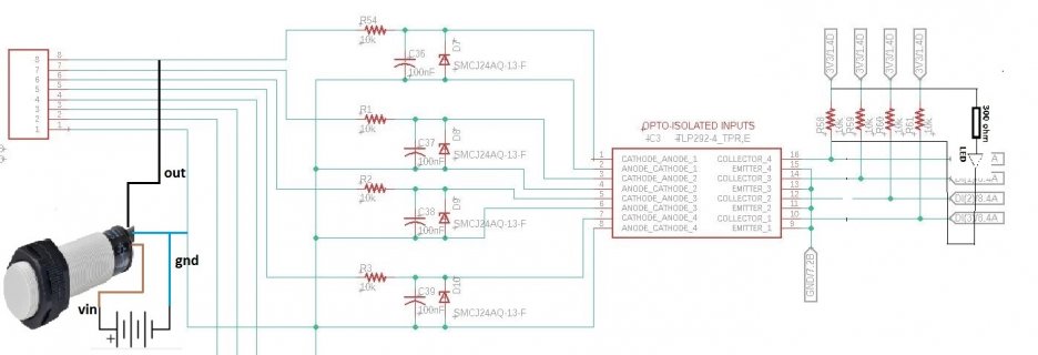
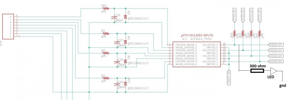
I'm attempting to monitor the status of a Capacitive Proximity sensor via one of the Teensy 4.0 Digital Inputs. To ensure isolation between the input and the controller side, I've employed an opto coupler. I've attached the schematic I've been utilizing. Despite this setup, the LED connected to the digital pin isn't illuminating. Upon measuring the voltage across the digital pin during a logic HIGH state, I observed a drop of 1.8V. Could someone kindly provide insight into why the LED fails to illuminate?

Additionally, I require some information: Can I interface an Inductive Proximity sensor alongside the Capacitive Proximity sensor, as depicted in the attached schematic?
attaching the code, hope it is correct
Code:
int inPin = 14;   
int val = 0;     

void setup() {
 
  pinMode(inPin, INPUT);   
}
void loop() {
  val = digitalRead(inPin);   // read the input pin
   if(val==LOW){
        Serial.println("LOW");
  }
    else{
        Serial.println("HIGH");
        
    }
}
 

Attachments

  • DI.JPG
    DI.JPG
    114.6 KB · Views: 22
I don't understand your schematic. You said you are using "a Capacitive Proximity sensor". But on the schematic, I see only resistors, capacitors, diodes, a quad optocoupler, a connector, and net names that imply connection to other stuff we can't see. I did not see anything on your schematic which looks like a sensor. Did I miss something?

What is the "Capacitive Proximity sensor" and how is it actually connected? Maybe part numbers or links to the hardware you're using would help? Or maybe a photo of the actual sensor hardware could make this clearer?
 
The collector pins have a 10k pullup. Are the signals coming in to that section actively driven high by your senor or are they open drain?
If open drain then that would explain the lack of LED, you have a 10k resistor in series with the LED, it's going to clamp the voltage at the collector terminal to the turn on point of the LED. The LED will be on but so dim it will look off.
 
What is the "Capacitive Proximity sensor" and how is it actually connected? Maybe part numbers or links to the hardware you're using would help? Or maybe a photo of the actual sensor hardware could make this clearer?
this is the sensor I'm using (https://robu.in/product/autonics-cr...-capacitive-proximity-sensor-pnp-no-shielded/)

I don't understand your schematic. You said you are using "a Capacitive Proximity sensor". But on the schematic, I see only resistors, capacitors, diodes, a quad optocoupler, a connector, and net names that imply connection to other stuff we can't see. I did not see anything on your schematic which looks like a sensor. Did I miss something?
So I made a pcb which accepts digital inputs (can connect proximity sensors), the attached schematic belongs to the pcb circuit, the capacitive
DI.JPG
sensor will be connected as per the image
 
Now I see how it should work. :)

The LED and 300 ohm resistor should connect between the collector and 3.3V. When the optocoupler turns on the collector is pulled to GND by the NPN phototransistor. So for the LED to show on condition, connect the LED+resistor between the collector and 3.3V.

You might also consider changing R1, R2, R3, R54 to 4.7K, assuming the "vin" power supply is 12V. This will give 2.5mA into the optocoupler. Or perhaps even use 2.2K so you have approx 5mA.

The TLP292-4 does not give a minimum required current as a simple number, but if you look at the charts on page 6, you can see 2mA is the lowest curve they specify (this is collector current and the CTR is 60% in the specs, so divide by 0.6 for LED current). You can take that as a pretty strong hint to use at least ~3mA current into the optocoupler input.

1714464303959.png
 
Last edited:
The LED and 300 ohm resistor should connect between the collector and 3.3V. When the optocoupler turns on the collector is pulled to GND by the NPN phototransistor. So for the LED to show on condition, connect the LED+resistor between the collector and 3.3V.
Please let me know whether the attached image shall make LED to glow when Logic HIGH is detected
You might also consider changing R1, R2, R3, R54 to 4.7K, assuming the "vin" power supply is 12V. This will give 2.5mA into the optocoupler. Or perhaps even use 2.2K so you have approx 5mA.
So, the PCB I designed shall be capable of accepting 5V,12V and 24V sensors, as per above calculation if Vin is 5V, then the current into optocoupler will be 0.765mA, so in this condition , the LED shall not glow. Am I right? I hope 750 ohm input resistor will allow, 30mA with 24V i/p,14mA with 12V i/p and 4.8mA with 5V i/p, will this combination is ok?
 

Attachments

  • DI.JPG
    DI.JPG
    124.3 KB · Views: 5
The website for that sensor says the minimum power is 10 volts.
That is for sensor,
My aim is to connect different sensors with relatively wide range of signal voltages (5V-24V)
Therefore, the optocoupler should turn on at sensor Voltages of 5V too. The maximum sensor Voltage is 24V. The input resistor value shall be such that the optocoupler has to be turned on even at sensor 5V range too.. Hope I'm clear now
 
This is how, field implementation shall be, both capacitive and inductive proximity sensor will be connected, both can be of 24V output type or one can be 24V and other can be 5V output type, so I have to make circuit which can accept both type of sensors as well as both type of sensor voltage, I want to know whether this schematic is capable of my requirement. still input resistor value has to be calculated
20240430_165034 (1).jpg
 
The CTR for _saturation_ is only 30%, so if you want the phototransistor properly on with 1mA, 3.3mA is required to the LEDs of the optocoupler. To work at 3mA at 5V you'd need about 1200 ohm series resistor, which at 24V would carry 20mA and need to be 1W or rating to avoid being super hot.

Alternatively just use a 5mA constant current diode? Then the voltage doesn't change the current, and the max dissipation at 24V is only 1/8W

Lose the Zeners, that opto coupler is back-to-back LEDs, no protection needed.
 
You should probably run some tests with that Kingbright LED. The specs say brightness is 10 to 25 mcd with 10 mA current. Maybe a lower current will meet your needs, or maybe not. Only you can make that judgement call.

If you need a relatively high LED current like 10mA, the most sensible design would add a buffer chip between the optocoupler output and the LEDs, so the buffer provides the LED current.
 
Back
Top