WS2811 on Teensy 3.0 using FastSPI_LED library

Status
Not open for further replies.
Thanks for the prompt reply, and thanks again for taking it upon yourself to create the libraries. As long as its updated by Burningman I'll be smiling.
 
Yes, the high performance library is currently in private beta testing.

The testing has taken a little longer than I had originally hoped, but the good news is some bugs and usability problems have been fixed. I believe you'll be much happier with it, when released, than would have been the case without all this testing.

I'm planning on releasing on Feb 25. It will be announced first on this thread, and then on a couple major blog sites. I really do not like vaporware, and lately some major sites carried articles about completely untested WS2811 ideas.... so I'm trying to keep this stuff a bit quiet until release.

Follow this thread if you want to hear about it the moment it's available.
 
I'm confused now. It says: "64pcs 5050 RGB LED With 60pcs WS28IC inside to drive 64 pixels".

So how can it have 64 LEDs whilst there are only 60 controllers, per meter?

On the surface, it does look a bit different from what I ordered: http://www.aliexpress.com/snapshot/213954944.html

Can anyone shed some light on this?

Pretty sure that this is just a copy/paste error from the original 60 pixel strips. If you look carefully at the pictures, you can see that the new 64 LED strip has condensed the cut-point pads into a single pad, so if you want to split the strips, you have to cut down the copper, instead of between the pads as before. Honestly, I don't think the extra four pixels is worth the almost five dollars/meter mark-up.
 
I purchased 1920 of the cheapest LEDs from Ray Wu on Alibaba. I should have bought some spares. It turns out a few of the pixels have trouble. My best guess is they overheat. When it stops working, all the subsequent pixels after it in the strip stop getting data.

The power supplies, which came from a USA-based EBay seller (reselling the same cheap stuff from Alibaba merchants) have a trim pot to adjust the voltage. The default was 5.2V. When I reduced it to 4.8, 2 of the 3 "bad" pixels got better. One still stops working after about 2 hours, the other seems pretty happy at 4.8V. However, the worst pixel stops working within minutes, even at 4.8.

Those power supplies also had trouble. They were designed for a 120 / 240 volt switch, but the 3 I received had the switch missing. They worked at light loads, but beyond about 5 amps, they lost regulation and output only 4 volts. I did not test with heavier loads. Instead, I opened all 3 and soldered a wire at the empty place where the switch should have been.

The obvious point is these cheapest no-name products sometimes have pretty substantial quality problems. Then again, if you're building a very large LED project, the savings is so much that it may be worth the hassle. Just be sure to buy a few spares..... I did not, but should have.
 
Last edited:
I purchased 1920 of the cheapest LEDs from Ray Wu on Alibaba. I should have bought some spares. It turns out a few of the pixels have trouble. My best guess is they overheat. When it stops working, all the subsequent pixels after it in the strip stop getting data.

The power supplies, which came from a USA-based EBay seller (reselling the same cheap stuff from Alibaba merchants) have a trim pot to adjust the voltage. The default was 5.2V. When I reduced it to 4.8, 2 of the 3 "bad" pixels got better. One still stops working after about 2 hours, the other seems pretty happy at 4.8V. However, the worst pixel stops working within minutes, even at 4.8.

Those power supplies also had trouble. They were designed for a 120 / 240 volt switch, but the 3 I received had the switch missing. They worked at light loads, but beyond about 5 amps, they lost regulation and output only 4 volts. I did not test with heavier loads. Instead, I opened all 3 and soldered a wire at the empty place where the switch should have been.

The obvious point is these cheapest no-name products sometimes have pretty substantial quality problems. Then again, if you're building a very large LED project, the savings is so much that it may be worth the hassle. Just be sure to buy a few spares..... I did not, but should have.

You can cut out the offending pixels and solder the strip back together.
 
I had similar issues and had to cut out the bad pixels. This problem was limited to only one of the rolls that I purchased.
Fortunately for me the supplier is replacing the roll.

I suspect that most users of these lightstrips aren't providing enough current to push the strips to their maximum design specifications.
A typical 60 pixel/meter strip, at full white (255,255,255), draws more than 3.5 Amps per meter... Way more than your average wall wart can provide.

I guess Burn-in testing may be apropriate for critical, or or inaccessable projects.

BTW, Has anyone figured out how to get long lengths back in their silicone jackets after repairing the waterproof models?

Paul, I can send you a few spares to use as replacement pixels if you'd like.
 
BTW, Has anyone figured out how to get long lengths back in their silicone jackets after repairing the waterproof models?

You just sort-of wiggle it in. You gently grip the jacket by the edges, and let the thing hang vertically. Then, pinching the strip between the lights, you just slide it in. If you get stuck, pull out a little and wiggle it, then try sliding it in again. Another approach to consider (I haven't had to do this, so YMMV), is to attach a string to the end of the lights, thread that through the jacket (with a long stick or something), then pull the lights through.
 
Mine must be a tighter fit... I can only wiggle them in about 25cm before they bind and kink.
I'll try the string idea...or maybe solder a long wire.
thanks
 
tumblr_m22bfe9txl1qa10uwo1_500.png
 
Wozzy, the FastPIN and FastSPI pieces are part of FastSPI_LED2 - and if you use just the Pin or the SPI parts, the other parts aren't included/compiled in. (Well, that isn't, strictly speaking, entirely true - if you use just the FastSPI (non-led) part, then some of the Pin code is compiled in as well, since they build on each other). So, you get one, you get all three.

Right now the Pin/SPI libraries are output only (courtesy of the focus on the led library). However, my plan is to make them also work with input ASAP (though, in practice, that might be a few weeks - I have a diving trip i'm going on next week!)
 
I just saw your writeup via Hackaday. Great stuff. I am actually working on some custom 8x8, 16x16, and 24x24 pcb boards. All the matrices will have 12.5 mm spacing in x-y direction. I have been wanting to put together a 128x64 led matrix (5’x2.5’) in size for awhile now. Power managment is key with these leds. I also plan on offering these matrices for sale at some point. Anyways, I wanted to say great work on your libraries. I had been wanting to implement a “parallel” type output for a bit.

Looks like I am going to have to get some teensy's on order! In the meantime here's a prototype of the 8x8 board https://vine.co/v/bna0mTg9ZZ3
 
Wow. Absolutely great work, PaulStoffregen.

I was playing with a teensy 2.0 and some ws2811 led's for a few days (which ended up working thanks to Alan's code over here.)

Now I read about your library on hackaday I will be getting "some" teensy 3.0's. You state "Any number of Teensy 3.0 boards may be used to support large LED arrays." ... so how many is any?
Have you done some calculations as to what's the maximum number of led's you can drive - keeping in mind other bottlenecks as USB and a sensible framerate (100fps for fast animations?).
 
From looking at the library code, and what little I know about it, I think your wallet will be the primary limiting factor in the number of teensy3's/LED's in your project, and after that, would be USB bus bandwidth, which can be worked around by adding more root USB ports to the host machine. Also, if memory serves me right, I think in one of his previous posts he stated that ram was the primary factor limiting the number of LED's a single teensy3 could address. Right now he states it's about 1000 per teensy3.
 
As you scale up to an extremely large LED array, eventually a few technical problems will come into play.... other than the obvious issues of material cost, huge power requirements, and the sheer number of hours needed to build the system.

USB bandwidth is the main technical issue. With 30 Hz video, each Teensy gets 180 kbytes/sec, and if you play a 60 Hz progressive video, it’s 360 kbytes/sec. Teensy 3.0 can easily handle these speeds, because each runs completely separate, other than listening for the frame sync pulse. The main reason for the 1000 LEDs per Teensy guideline is so each board can easily accomplish its job with plenty of timing margin, even if there is some extra USB latency. If there is scheduling latency of other temporary software lag on the computer (eg, Java's garbage collection), and then it transmits one or more frames too rapidly, the timing margin greatly improves the whole system's robustness. The USB bandwidth plus timing margin is main reason for the 1000 LEDs per Teensy guideline. In theory, you might be able to connect more than 1000 and maybe still be ok, but at $19 each compared to at least a couple hundred dollars for the LEDs, you really will not save much connecting more LEDs per Teensy. I personally test OctoWS2811 with 960 LEDs connected to each Teensy, so I highly recommend you follow the 1000 LEDs per Teensy guideline for best performance and compatibility.

Somewhere around 20 to 40 Teensys, the total data flow is going to become a substantial part of USB 2.0 bandwidth. You probably want to keep the total under half of USB’s capacity. You might need USB 3.0, or add extra USB 2.0 cards. Typically all the USB 2.0 ports on a computer share the same 480 Mbit/sec bandwidth.

You must use good quality USB hubs. 
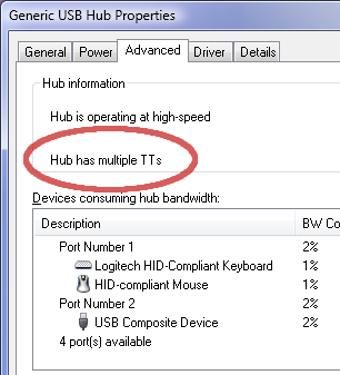
Beware of single-TT USB HUBs. They will cause problems. Only Multi-TT hubs properly share bandwidth. A USB "TT" is the Transaction Translator (basically a buffer memory and some logic) which converts between USB speeds. Sadly, very few hubs actually say which type they are... the marketing is all based on size, shape & color. But there are indeed 2 types of USB hubs and it does make a dramatic difference for a system like this. You can check which type a HUB actually is with Linux's "lsusb -v" or Windows 7's device manager.

td_flightsim_4.png


If the display is incredibly large (more than 8 meters wide) and you have Teensy 3.0s located on both the left and right sides, USB cable lengths might become an issue? You might need to locate the PC in the center behind the display and run 2 long cables to a hub on each side, or perhaps a hierarchy of USB hubs on each side? Especially if using USB 3.0 to the first tier, and perhaps USB 2.0 in the 2nd tier, and then those hubs driving the Teensy boards, be aware of the USB cable lengths and use good quality cables.

Another issue is transmitting the frame sync signal. At some point, perhaps even as few as 8 boards, you’ll probably need to use a 50 to 100 ohm resistor on the frame sync pin. This is more a function of the physical wire you use. Using a good quality cable like CAT5 twisted pair with the ground and frame sync on a pair will help. If the wire runs a different path than the ground (as I did in this 1920 LED demo), the signal can get ringing and other transmission line effects.

At huge sizes, the you’ll probably need to add buffer chips to transmit the frame sync pulse to each group of other boards. This too is pretty easily solved. However, with only a wire, it doesn’t matter which board is the master sending the pulse and which others receive it. That makes things very easy, where you can just plug the boards in any order and no worry which ones get assigned to which device names or com port numbers. If you add unidirectional buffer chips like a 74HC245, then it’ll become important to make sure the intended board is the master. The first board in the list in movie2serial’s setup() is the master. You’ll just need to make sure the port corresponding to the board with those buffers is listed first.

A really good, but perhaps overly conservative approach to the frame sync would involve using RS-485 on a twisted pair cable. Still, if you're connecting over $10000 in LEDs, this might be worth considering. The digital pins from Teensy 3.0, and even buffer chips like a 74HC245, aren't meant to drive really long cables. RS-485 signals are designed for fast performance over thousands of feet of cable. You would need to make 1 driver board and a receiver board for each Teensy, so this is adds quite a bit of work, but it automatically handles this next issue...

At the incredible amount of current consumed by tens of thousands of LEDs, another possible issue you may face is differences in the ground potential. For example, a system using 40 Teensy 3.0s would be driving approx 40000 LEDs, which could consume about 2000 amps of current at 5 volts when all are driving fully white. Obviously you'll locate many power supplies as close as possible to the strips they power. You'll use #22 to #18 wire between the power supplies and the LEDs (a 1 meter strip of 60 draws up to 3 amps). But it's important to keep in mind the whole system's grounding. When we draw schematics, we put ground symbols all over the place and assume they're all at exactly the same potential. But in reality, electrons flow through metal that have non-zero resistance. Certainly you should measure both AC and DC voltage between "ground" at distant locations as the LEDs change power usage. You may need to add extra ground wires to keep the whole system at the same ground potential, or within 100 to 200 mV, so the USB can work.

The huge power requirements should be obvious, but just to mention it again, 40000 LEDs using 80% efficient power supplies (which hopefully have inrush limiting and active power factor correction) will draw about 52 amps at 240 volts AC. This much power would normally be supplied by a 3-phase service, where you'd probably run the many power supplies in 3 groups at 208 or 277 volts, depending on the type of service.

The final problem, which I doubt would ever be an issue on any modern computer, might be lack of CPU time to process the original video material into the many streams for each board. The code might need to be rewritten in C. However, running on a MacBook Air (certainly not the fastest machine), the 1920 LED demo was using 8% CPU time. I didn’t investigate the CPU usage in detail, but it was approximately the same just running without sending to any boards, so most of that 8% is probably the video decode, screen updates, or other stuff Java and Processing are doing to play the video. Still, each Teensy needs some CPU time on the machine sending the video, so as you scale up, keep an eye on how much of your computer's resources the software is using.

These limits come into play for extremely large displays, probably involving over $10000 in LEDs. If you use OctoWS2811 for such an awesome project, you really must send me photos!!!
 
Last edited:
Wow. This is great stuff. I wish I understood more about how it all works.

How hard will it be to port this library to other LED strips? (like the LPD8806 or others). Is there a way to abstract the output or is it very specific to the WS2811s?

The reason I ask - I have access to some LED panels from a now out-of-business company that did video walls and other big LED installations. The LED panels are 256 RGBs on a 15x15 inch frame (one 16x16 grid per panel).

With the help of a friend I have the AdafruitGFX library ported to these panels and I can make basic animations or push images from an SD card.

The past 2 days I put together a patch in MAX to push video to my Teensy3 and then use SPI out to the LED panels..., but I'm seeing the frame rate suffer as I add more LEDs.

Thus - I'm looking for more efficient solutions to move the data

Here's a video I made last night with 6 panels (32 x 48 pixels) = 1536 pixels
http://www.youtube.com/watch?v=t0tQTypWuBc
 
Last edited:
How hard will it be to port this library to other LED strips? (like the LPD8806 or others). Is there a way to abstract the output or is it very specific to the WS2811s?

OctoWS2811 is very specific to driving exactly 8 strips the WS2811, thus the name "OctoWS2811".

About a year ago, I wrote a program for streaming video to LPD8806 strips. Well, at least the Teensy side. It only converts incoming USB to 8 bit parallel output (the data is never stored into Teensy's RAM), so you can't build a stand-alone program like with OctoWS2811. This LPD8806 stuff was never turned into a nice, well documented library, but at least a couple people used it for very large LED projects. Here's some links for you:

http://forums.adafruit.com/viewtopic.php?f=47&t=25854&p=143049#p143049

http://www.dorkbotpdx.org/blog/armatronix/led_video_wall

http://hackrockcity.org/post/24363042425/domestar-may-2012-domestar-appeared-on-the

The OctoWS2811 approach might be able to work for LPD8806 strips, with the DMA code redesigned. But that would take quite a lot of work. Since the WS2811 is now much less expensive and therefore much more popular than the LPD8806, it seems unlikely OctoLPD8806 will ever be written. But the code at those links above is real and as you can see from the video wall and Domestar, it definitely does work.
 
Thanks Paul... I looked at domestar stuff awhile back and I'm looking over the other links now.

FWIW - I'm trying to see what I can accomplish with these crazy LED panels I have so I'm looking to find techniques I can borrow from existing code. The serial2parallel code you posted in that forum link might be pointing me in the right direction.

Cheers!
 
Really thorough answer to my question

^^ Thanks a lot.
Well it looks like there could be a project coming my way for building a whole LED wall. I'll take all your advice into consideration and will of course let you know how it goes - if it happens.
 
Status
Not open for further replies.
Back
Top