touchRead and I2C

Status
Not open for further replies.

Plocploc

Member
Hello,

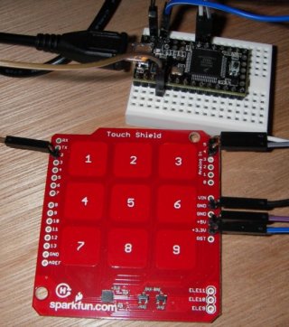
I'm trying to make a capacitive keypad using teensy 3.0 and a Sparkfun touch shield board. Since it's I2C based, I've only wired its SDA (A4), SCL (A5), 3.3V and GND to the appropriate teensy pins (SDA>18, SCL>19) as shown in the photo below.
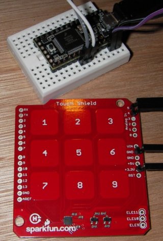
Imgp0876.jpg

As for my first test program, I'd like to print a number (or any char) when touching a key on the Sparkfun pad.
But the problem is that I'm struggling to figure out how to use the touchRead() function.
- Should I touchRead the SDA or SCL pin?
- Also, the technical document said the Sparkfun I2C address is 0x5A, so I guess I'll have to use this somewhere, somehow.

I'd be grateful if someone could enlighten me a bit. Of course I forgot to say my knowledge about I2C is quite... basic and poor.
Thanks in advance.
 
Teensy 3.0 has touch sensing built in. You use the touchRead() function when an electrode is connected directly to one of the touch capable pins.

This shield has the electrodes connected to a special chip. To use this shield, you need to communicate with that chip. So do not use touchRead() with this shield.

First, connect Teensy 3.0's 3.3V power to both 3.3V and 5.0V on that shield. I know it says 5V, but it's only connected to the pullup resistors. You need those to have 3.3V for the I2C communication to work. (It's a very good thing you posted the photo with at least a small part of the wires shown)

Sparkfun's example code will not work on Teensy 3.0, because it directly accesses the I2C using the 8 bit AVR registers. But it should be possible to convert to using the Wire library.

Start by deleting the file i2c.h, and delete the line #include "i2c.h" in the main program. This will get rid of all the AVR-specific code.

Add a #include <Wire.h> line at the top.

Replace i2cInit(); with Wire.begin(); in the setup function.

Then you'll need to replace the 2 functions which access the chip. Here's my best guess:

Code:
byte mpr121Read(uint8_t address)
{
  Wire.beginTransmission(0x5A);
  Wire.write(address);
  Wire.endTransmission(false);
  Wire.requestFrom(0x5A, 1);
  return Wire.read();
}

void mpr121Write(unsigned char address, unsigned char data)
{
  Wire.beginTransmission(0x5A);
  Wire.write(address);
  Wire.write(data);
  Wire.endTransmission();
}

Of course, I do not have one of these shields to test. Please let me know if this works?
 
Also, delete these 2 lines:

Code:
  DDRC |= 0b00010011;
  PORTC = 0b00110000;  // Pull-ups on I2C Bus

They probably do not matter, but they're certainly not helping!
 
Thanks a lot for your instructions. I'll do that tomorrow and check. Back from work too late today and had some virus problems :-\
 
I've connected both the 5V and 3.3V pins of the Sparkfun board to the Teensy 3.3V, and changed the code as you said. It doesn't seem to work.
So I tried to insert a debug line and see whether it would detect a "touch press", i.e. check the value of the touchstatus var (I left 3 fingers on 3 random keys during all the test time)

Code:
void loop()
{
  Serial.println (getNumber());
  delay(1000);
}

uint16_t  getNumber()
{
  int i = 0;
  int touchNumber = 0;
  uint16_t touchstatus;
  char digits[DIGITS];
  
  touchstatus = mpr121Read(0x01) << 8;
  touchstatus |= mpr121Read(0x00);
  return(touchstatus);

Of course I replaced and used the mpr121Read() function you suggested. But in the console, the touchstatus value never changed from 0. So, either:
1) there are soldering/wiring problems with my board
2) or the Teensy couldn't read the Sparkfun correctly.
I wish there was a LED on the Touch Shield so I could know whether it's correctly powered and working...
I'll look into this more thouroughly tomorrow

PS: by the way, I was wondering about the interrupt pin (D2). Should I connect it, too? I keep seeing comments in the Sparkfun code about IRQ
 
Well, that's pretty weird.
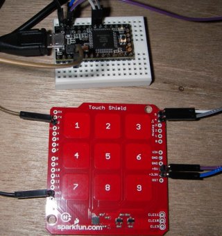
I've been to the Sparkfun quickstart guide here and done all the required wiring to the Teensy (see photo below)
SDA and SCL wired => OK
GND to Teensy AGND => OK
Both 3.3V and 5V to Teensy 3.3V => OK
IRQ pin (D2) to Teensy D2 pin => OK

Imgp0878.jpg

I've compiled their code successfully and uploaded to the teensy
Code:
void setup()
{
  //make sure the interrupt pin is an input and pulled high
  pinMode(irqPin, INPUT);
  digitalWrite(irqPin, HIGH);
  Serial.begin(9600); //configure serial out
  Wire.begin(); // initalize I2C bus
  mpr121QuickConfig(); // initialize mpr121
  Serial.println("MPR121 Initialized. Press buttons!");
}

void loop()
{
  if (!digitalRead(irqPin))
  {
    getNumber();
  }
}

Actually I couldn't even get the "MPR121 Initialized. Press buttons!" message on the serial console.. So I wonder whether the init sequence passed.
There's also a very weird thing.
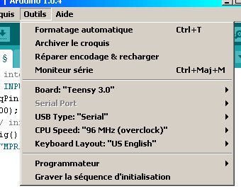
My IDE settings are:
- Board: "Teensy 3.0"
- Serial port: COM3 checked
- USB type: "Serial"
- CPU Speed: "96Mhz (overclock)"
- Keyboard layout: "US English"

Now, if I add a Serial.println ("Debug test") in the loop() function to test display on COM3, then "Serial port" in the Tools menu becomes grayed... Why?
teensy1.jpg

It would be hard to test anything if even the COM3 console won't display correctly :(
 
Actually I couldn't even get the "MPR121 Initialized. Press buttons!" message on the serial console.. So I wonder whether the init sequence passed.

It's very likely this printed and was long gone before you opened the serial monitor window.

Add a "while (!Serial) ;" line after Serial.begin and before you print anything. See any of the Arduino example for how it's done.
 
Well, I added that just before printing the "MPR121 initialized" thing.
But then, the Serial port menu became disabled (grey) and if I choose to open the serial console, the Arduino IDE would refuse and say "Serial COM3 not found. Did you select it in the Tools menu?"
Of course I couldn't choose it, since it's disabled.
 
Finally, I just set a delay(6000); in the setup() after the Serial.begin() and it displayed the MPR121 init message well. Also, about the disabled Serial menu, all I had to do was upload the program twice by pushing the Teensy button twice and it worked fine.
But now, the main probleme is that it doesn't detect any finger touch.. Maybe I should check my wires and jumpers again.
 
Yeeepeeekay! Well, I was such a dumb. Actually I was looking at my soldering, and I noticed that only the significant pins had a track on the PCB. And the GND pin I soldered the header to had nothing. So I decided to use another GND pin that had apparent track on the PCB. And voila! That would teach me to look more closely.
The Spakfun board has only 1 "working" GND out of 3. Anyway, it's working like a charm now.
Once again, thanks a lot for your patience and valuable help/advices Paul. Much appreciated :)
 
Could you post the final confirmed-good code and a photo of how it's hooked up? And post a comment on Sparkfun's page linking to this writeup? Hopefully if anyone else tries the same thing, they'll find your comment and it might help?
 
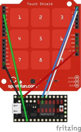
Wise indeed. Here are the correct pins to solder. As for the code, I got it from their quickstart download site, and didn't modify anything.
I'll also post a comment on their product page linking to this.
Imgp0880.jpg
 
Teensy 3.0 has touch sensing built in. You use the touchRead() function when an electrode is connected directly to one of the touch capable pins.

Is there any documentation on using the touchread() function? Which library is it in? Example code? Does it support proximity as well as touch?

Any help would be greatly appreciated.
 
Status
Not open for further replies.
Back
Top