Latest activity
-
 mjs513 replied to the thread Call to arms | Teensy + SDRAM = true.Testing the different cameras on the SDRAM board became problematic - not sure if wiring/connector issue but alot of problems we were seeing was with the wiring as @KurtE mentioned on the camera thread about wiring. So we decided to make a...
 -
-
Sshawn replied to the thread NativeEthernet.h hangs NativeEthernet.cpp, while(!link_status){ } (line293) WHY???.I think it was an attempt to make the library behave the same as a remembered past version, for compatibility with existing past code. A post with some history: https://forum.pjrc.com/index.php?threads/compiler-error.73841/post-333932 An...
-
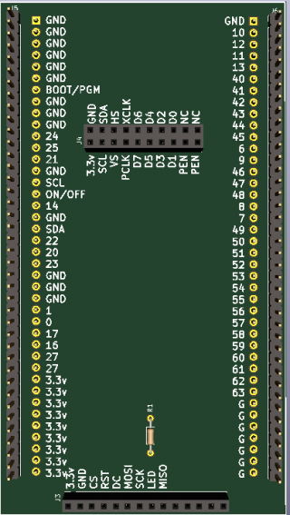
 @KurtE and I have been at it again. This time creating a library that supports a number Arducam/Arduino camera modules: Model FrameSizes Pixel Formats Omnivision OV2640 FRAMESIZE_VGA //640x480 FRAMESIZE_QQVGA, // 160x120...
 -
Thanks @mjs513, As you mentioned we are having some fun with several of these cameras. I see you showed my quick and dirty (v2) version of a shield for the Sparkfun Micrmod ATP board. Sure is a lot easier than having to deal with lots of...
-
mjs513 reacted to PaulS's post in the thread Magnetic Encoder not working with teensy 4.1 but is with teensy 3.2 with
 Like.
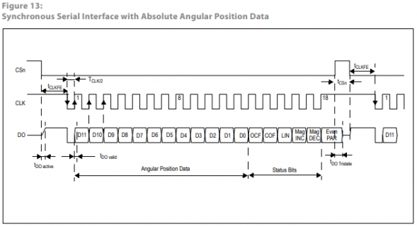
Since a Teensy 4.x is so fast, I would add a delayMicroseconds(1); after the clockpin going low as well, like so: uint32_t SPIencoder::readRegister(void){ // Initiate variables uint8_t inputstream = 0; int outputVal = 0; uint8_t...
Like.
Since a Teensy 4.x is so fast, I would add a delayMicroseconds(1); after the clockpin going low as well, like so: uint32_t SPIencoder::readRegister(void){ // Initiate variables uint8_t inputstream = 0; int outputVal = 0; uint8_t... -
PaulS replied to the thread Magnetic Encoder not working with teensy 4.1 but is with teensy 3.2.Since a Teensy 4.x is so fast, I would add a delayMicroseconds(1); after the clockpin going low as well, like so: uint32_t SPIencoder::readRegister(void){ // Initiate variables uint8_t inputstream = 0; int outputVal = 0; uint8_t...
-
-
Vv1studio replied to the thread porting schetch 3.6 to 4.1.I tried to load the sketch, inserting in some strings, otherwise it wouldn't pass the check, but the problem remains. The only difference noted is that if I try to calibrate the signal as in the video I can make the signals go with 0-50-100%...
-
Cchrissaich posted the thread Problem installing Arduino IDE 1.8.19 and Teensyduino 1.59 on RPI5 Bookworm in General Discussion.I'm running Arduino IDE 1.8.19 and Teensyduino 1.59.0 on a clean install RPI5 Bookworm running on an m.2 nVME hosted on PCIExpress bus. After a number of false starts, I've loaded Arduino IDE and Teensyduino using a script from Paul Stoffregen...
-
 Davidelvig reacted to PaulStoffregen's post in the thread SGTL5000 Microphone Input - How long can the conductors be between mic and board? with Like.
10 inches is probably fine if you use shielded cable or twisted pair or even just 2 conductors held close together. What actually happens will really depend on whether your environment has something noisy which tends to couple to the wires...
Davidelvig reacted to PaulStoffregen's post in the thread SGTL5000 Microphone Input - How long can the conductors be between mic and board? with Like.
10 inches is probably fine if you use shielded cable or twisted pair or even just 2 conductors held close together. What actually happens will really depend on whether your environment has something noisy which tends to couple to the wires... -
 wwatson replied to the thread Call to arms | Teensy + SDRAM = true.What length wires are you using between the MCU and the display boards? WIth 10cm wires I could not get past 20Mhz when testing With an LCD and Micromod mounted to the same pcb with 2cm traces we got 24/30Mhz working. I am using the same length...
 -
mjs513 replied to the thread Magnetic Encoder not working with teensy 4.1 but is with teensy 3.2.Don't know much about this encoder to be honest but my guess the problem could be with the delays in this function: uint32_t SPIencoder::readRegister(void){ // Initiate variables uint8_t inputstream = 0; int outputVal = 0; uint8_t...
-
Thanks for the response. I wired up the dev board again and started testing with the baseline driver code I posted. It shows something is wrong in the dev board/MicroMod side of my code. No matter what I set the bus speed to loading the same...
-
mjs513 replied to the thread New Camera Library for Teensy Micromod/4.1.Thanks Kurt - probably should add some of this to the repo on the examples :) Anyway for those of you that don't know about the projects I mentioned earlier, they all use single class, #include "Camera.h", to call the different cameras and if a...
-
 BriComp replied to the thread porting schetch 3.6 to 4.1.You have the code below in your setup...... Serial.begin(baud); HWSERIAL.begin(baud); #ifdef INCLUDE_WS2812B WS2812B_strip.begin(); WS2812B_strip.setPixelColor(0, 0, 0, 0); WS2812B_strip.show(); #endif rotary_initHalf()...
 -
 PaulStoffregen replied to the thread Getting issue while flashing code on Teensy4.0 board.To troubleshoot, try adding delay at startup to give enough time for the USB enumeration to complete. Usually 1.5 seconds is enough for Linux. You might need 2.5 seconds or more for Windows. If the problem is happening inside a C++...
 -
Rrevati replied to the thread Getting issue while flashing code on Teensy4.0 board.Thanks, it works.
-
TTonton replied to the thread New Teensy 4.1 DIY Synthesizer.It's original file, then the same issue, slanted screen
-
PaulStoffregen replied to the thread Getting issue while flashing code on Teensy4.0 board.Programs which crash too early do this. Please try loading a simple "Hello World" program, without FreeRTOS and CAN libraries, just to confirm the upload process and serial monitor are still working. If not, please try testing with Arduino IDE.
-
VHi guys, I have a problem with this mentioned scheme. When I try to calibrate the analog signal (A0 and A1) with the Teensy 3.6 it works correctly but with the 4.1 it doesn't. Compared to the video in the link (video) which is working with...
-
Kkd5rxt-mark replied to the thread NativeEthernet.h hangs NativeEthernet.cpp, while(!link_status){ } (line293) WHY???.@Garug: Maybe try using QNEthernet (newer/better Ethernet stack, excellent examples available, actively maintained by @shawn who is on this forum) instead of NativeEthernet (older). See <this> thread for specific mention of the problem that you...
-
PaulStoffregen replied to the thread SGTL5000 Microphone Input - How long can the conductors be between mic and board?.10 inches is probably fine if you use shielded cable or twisted pair or even just 2 conductors held close together. What actually happens will really depend on whether your environment has something noisy which tends to couple to the wires...
-
Jjean posted the thread file compilation, download, boot on external flash memory in General Discussion.Hello everyone, my research is really struggling to progress due to lack of skills on my part! (I read a lot on this forum and on Google) I still managed to connect a W25Q64JVSSIM flash chip to my Teensy 4.0 board. I will order a W25N01GVSFIG...
-
RRezo replied to the thread Call to arms | Teensy + SDRAM = true.It's hard to troubleshoot these things online, but can yo do a simple test with a logic analyzer? similar to what I did here? We need to verify that the data is being sent out in the correct order. The DMA is set up specifically to accept a 16...
-
GGarug replied to the thread NativeEthernet.h hangs NativeEthernet.cpp, while(!link_status){ } (line293) WHY???.I found kind of workaround, I am using fixed IP, with it, it does not seem to get through unless link status ok. but like this it gets past the Ethernet.begin after a minute or so even when cable not connected. (this is on Teensy 4.1) //setup...
-
GGarug posted the thread NativeEthernet.h hangs NativeEthernet.cpp, while(!link_status){ } (line293) WHY??? in Technical Support & Questions.The NativeEthernet.h hangs at Ethernet.begin( unless the Ethernet cable is connected and link ok. the NativeEthernet.cpp seems to have while(!link_status){ } (line293) WHY??? how am I supposed to get on setup past Ethernet.begin( if the...
-
Rrevati posted the thread Getting issue while flashing code on Teensy4.0 board in General Discussion.Hi all, I am trying to flash code on Teensy4.0 every time it is stuck after Rebooting..... it is waiting to push reboot button and then it is flashing the code. But after that when i am opening serial monitor to see output nothing is printing...
-
 defragster reacted to KurtE's post in the thread New Camera Library for Teensy Micromod/4.1 with Like.
Thanks @mjs513, As you mentioned we are having some fun with several of these cameras. I see you showed my quick and dirty (v2) version of a shield for the Sparkfun Micrmod ATP board. Sure is a lot easier than having to deal with lots of...
defragster reacted to KurtE's post in the thread New Camera Library for Teensy Micromod/4.1 with Like.
Thanks @mjs513, As you mentioned we are having some fun with several of these cameras. I see you showed my quick and dirty (v2) version of a shield for the Sparkfun Micrmod ATP board. Sure is a lot easier than having to deal with lots of... -
Jjizquie3 posted the thread Magnetic Encoder not working with teensy 4.1 but is with teensy 3.2 in Suggestions & Bug Reports.Hello everyone, Im currently working on a part of a big project that requires me to read the the absolute position of a magnet that's being read on an encoder. I'm using a Teensy 3.2 but want to move over to using a teensy 4.1. The reason why...
-
Jjmarsh replied to the thread New Camera Library for Teensy Micromod/4.1.You can manually change the FlexRAM config (in the linker script) to assign some of the 512KB to OCRAM2, which exists in memory directly after regular OCRAM (DMAMEM)... effectively enlarging it.
-
Davidelvig posted the thread SGTL5000 Microphone Input - How long can the conductors be between mic and board? in Project Guidance.I'd like to connect a simple Electret Condenser Microphone to the MIC inputs of the SGTL5000. How long can my leads be? The pins are up to 10" away from where I want a microphone.
-
 KurtE replied to the thread New Camera Library for Teensy Micromod/4.1.Thanks @mjs513, As you mentioned we are having some fun with several of these cameras. I see you showed my quick and dirty (v2) version of a shield for the Sparkfun Micrmod ATP board. Sure is a lot easier than having to deal with lots of...
 -
wwatson replied to the thread Call to arms | Teensy + SDRAM = true.Thanks for the response. I wired up the dev board again and started testing with the baseline driver code I posted. It shows something is wrong in the dev board/MicroMod side of my code. No matter what I set the bus speed to loading the same...
-
-
TThis is something I have been working on for a while now. BitByte is a development console designed to make it easier to learn how to program and a platform made for creating and sharing games and programs for breadboards. Utilizing a custom...
-
Aanatoledp replied to the thread BITBYTE : LEARN CREATE PLAY.my goodness u have no idea how grateful I am for that. Marketing is in no ways my strong suite so that was so needed and appreciated. I really only thought u might post the original stuff in your forums because (at least from my perspective) its...
-
PaulStoffregen replied to the thread BITBYTE : LEARN CREATE PLAY.As usual for blog articles, shout-out on 4 social networks https://bsky.app/profile/paulstoffregen.bsky.social/post/3kqe6a5mq432f https://mastodon.social/@PaulStoffregen/112288541665182235 https://www.facebook.com/groups/1470129233297275
-
RRezo replied to the thread Call to arms | Teensy + SDRAM = true.@wwatson the code looks good from a brief overview. What length wires are you using between the MCU and the display boards? WIth 10cm wires I could not get past 20Mhz when testing With an LCD and Micromod mounted to the same pcb with 2cm traces...
-
Aanatoledp replied to the thread BITBYTE : LEARN CREATE PLAY.Yeah i initially was going to post it on the other one but after reading the tooltip for general decided it was better to be posted here. Just didnt think about closing it off as I was called away to other things and forgot.
-
Aanatoledp replied to the thread BITBYTE : LEARN CREATE PLAY.Ayo didnt expect you to put a kickstarter link in it as well. Thanks very much for that :D . . .
-
PaulStoffregen replied to the thread BITBYTE Development Console.Let's continue any conversation about BitByte on your other thread. https://forum.pjrc.com/index.php?threads/bitbyte-learn-create-play.74870/ I'm going to close this prior thread.
-
PaulStoffregen replied to the thread BITBYTE : LEARN CREATE PLAY.Article posted on the website today. https://www.pjrc.com/bitbyte-handheld-console/ Hopefully it helps your Kickstarter campaign! :) I see you have another older thread...
-
PaulStoffregen replied to the thread BITBYTE Development Console.Article posted on the website today. https://www.pjrc.com/bitbyte-handheld-console/ Hopefully it helps your Kickstarter campaign! :)
-
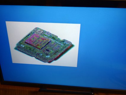
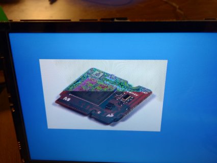
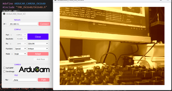
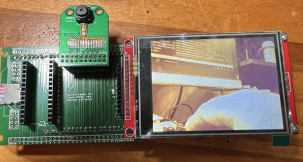
mjs513 replied to the thread New Camera Library for Teensy Micromod/4.1.To give you an idea ran the OV2640 camera using the Aducam at SVGA resolution with an antique special effect in jpeg format Same JPEG image downsampled on a ILI9341:
-
-
wwatson replied to the thread Call to arms | Teensy + SDRAM = true.That's why I hope Rezo can go over the low level drivers I posted to make sure I am not missing something. I have a general idea of how FlexIO works but I might be missing some little details. Meanwhile I am wiring up the DevBoard again to test...
-
@KurtE and I have been at it again. This time creating a library that supports a number Arducam/Arduino camera modules: Model FrameSizes Pixel Formats Omnivision OV2640 FRAMESIZE_VGA //640x480 FRAMESIZE_QQVGA, // 160x120...
-
Davidelvig posted the thread [Moved] SGTL5000 Microphone Input - length of conductors between mic and board in Audio Projects.I'd like to connect a Electret Condenser Microphone to the MIC inputs of the SGTL5000. How long can my leads be? The pins are up to 10" away from where I want a microphone. I moved this to Project Guidance
-
Davidelvig replied to the thread EWI mouthpiece with breath and bite (lip pressure) sensors.Hey, @arion_s, I'd love to swap stories. I've built a trumpet-like wind controller and I'd like to learn your experiences on the sax-like EWI controller. PM me here if you'd like to chat.
-
defragster replied to the thread Call to arms | Teensy + SDRAM = true.Except for the SDRAM added connects as noted in p#926 - the majority of the pins present as a micromod since it is seen as T_MM because of the use of the 16MB Flash. Wonder if anything in the #IFDEF T_MM code might make the difference? Otherwise...
-
 dimitre replied to the thread [solved] Teensy 3.2 SPI speed decreasing over time.Sure, I'll be sharing some videos soon! it is just a test to communicate with the LEDs. So it is a simple SPI connection on a protoboard. my real aim is use a 24v addressable LED chip (16 bits also) to drive some power mosfets with high PWM and...
 -
wwatson replied to the thread Call to arms | Teensy + SDRAM = true.I remember reading that. At this point I am not using the SDRAM at all with the display. It is strictly the traces between the 1062 MCU and the out side connectors of the board. Once that and DMA communications are solved then I can start testing...
-
PaulStoffregen replied to the thread Creating arbitrary waveform.I'm glad the FPU is working for you!