Latest activity
-
Ddarkextratoasty replied to the thread Running a timer off an external clock signal on Teensy 4.1?.It indeed appears that they will do exactly what I'm looking for. That is a tremendously helpful feature. I was just about to start searching for this information. Thank you for the quick, very helpful answer Paul. Now I need to do some...
-
TTallerdeteknologialibre replied to the thread Teensy 4.1 on macOS 10.13.Hi, it was the same issue as stated by others , i didnt know wich page was everyone reffering to Thanks for your reply! :)
-
TTallerdeteknologialibre replied to the thread Teensy 4.1 on macOS 10.13.Hi Paul , yes i figured out wich page where you referring , everything is functioning now Thanks
-
 PaulStoffregen replied to the thread Running a timer off an external clock signal on Teensy 4.1?.Some pin mapping info which might help: GPT2_CLK is on pin 14 (AD_B1_02 mux = ALT8) GPT2_CAPTURE1 is on pin 15 (AD_B1_03 mux = ALT8) GPT2_CAPTURE2 is on pin 40 (AD_B1_04 mux = ALT8) - Teensy 4.1 only
 -
PaulStoffregen replied to the thread Running a timer off an external clock signal on Teensy 4.1?.Quick answers I believe the GPT timers might able to do this. In the reference manual, see Figure 52-2 on page 3015, and section 52.3.1 on page 3016. The GPT timers are also 32 bits wide, which is much simpler than dealing with only 16 bits...
-
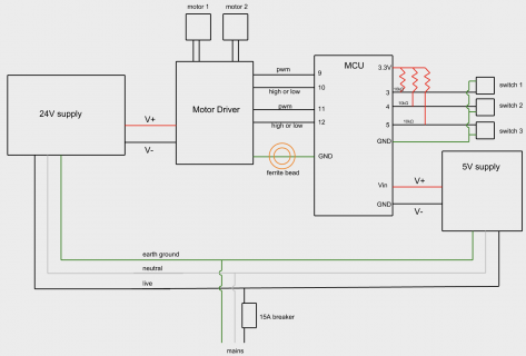
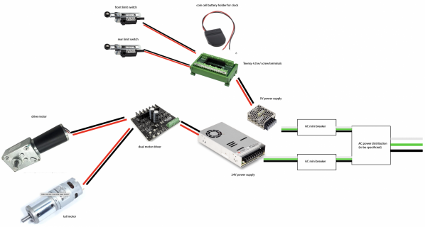
Bblinkypiper replied to the thread System works when powered by USB, but behaves weirdly on switching power supplies.Thanks so much for the quick reply, Paul. I'm embarrassed by the first drawing I posted, so I made a new and accurate one below. Both power supplies are connected to mains earth, but I'll double check all the connections to make sure they're ok.
-
-
PaulStoffregen replied to the thread System works when powered by USB, but behaves weirdly on switching power supplies.I don't see any connection in this diagram between Teensy and the dual motor driver. Assuming there is indeed a connection for Teensy to control the motors, check the GND wire. Perhaps GND is not properly connected between them? And maybe that...
-
Ddarkextratoasty posted the thread Running a timer off an external clock signal on Teensy 4.1? in Project Guidance.Can any of the timers within the Teensy 4.1 be incremented using an external clock signal, rather than the internal oscillator clock? My goal is to have a timer running off an external 10MHz square wave signal. I could then have a pulse on a...
-
Bblinkypiper posted the thread System works when powered by USB, but behaves weirdly on switching power supplies in Technical Support & Questions.Hello! I've found this forum incredibly helpful in the past, but this is my first time reaching out with a question. I'm working on a project that seems like it should be simple, but I'm being deviled by a problem that I think is electrical...
-
-
CI'm trying to use the ShiftPWM library to control 13 LEDs with 795 shift registers. I'm pretty sure I had this working a few months ago, so I suspect either I've done something wrong or an update to something has broken it. The compile error I...
-
DDeweyOxberger posted the thread Modifying USB descriptors well after enumeration in Technical Support & Questions.I'm looking for suggests on how to proceed here: A few seconds after boot I may find an I2C device connected to the Teensy 4.0 and it would be great if I could add a new device to the USB descriptors. The device is a variant of a HID device - a...
-
 ninja2 replied to the thread Still after help with sync to RTC on Wire2 in multi-tab sketch.Still looking for help with this ... perhaps if I re-word: To re-use my proven code with lots of "Wire." entries on Wire2 on my T3.6 I am using: #define Wire Wire2 but only in the RTC and EEPROM tabs, leaving the SSD1306 OLED on Wire0 This is...
 -
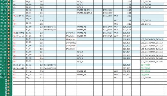
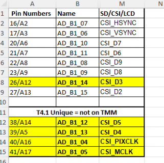
 I slightly updated @mjs513 copy of it he sent recently. In that I filled in more information about the newer pins I Hid most of the columns, which shows: The ones in Yellow are the ones we do not have. 3 are critical for CSI (D3-D5) The...
 -
 PaulS replied to the thread ArduinoMenu Library custom/dynamic menus.This example perhaps? Paul
 -
MMarkT replied to the thread U4 Chip gets extremely hot when 4.1 is connected to power..Connecting a motor direct to pin 8 of the Teensy? That doesn't sound safe, back EMF, burn out the pin through overcurrent, ESD through handling the motor - several ways this could be bad news.
-
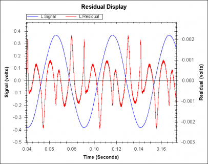
MMarkT replied to the thread Measured performance of line in and line out of SGTL5000.Yes, its an unmodified Audio adapter D that I've had for a while but only just soldered headers too and started using. Since the QA403 has high input impedance the caps distortion should be relatively low. I hope they are C0G/NP0 type...
-
-
 KurtE replied to the thread Call to arms | Teensy + SDRAM = true.I slightly updated @mjs513 copy of it he sent recently. In that I filled in more information about the newer pins I Hid most of the columns, which shows: The ones in Yellow are the ones we do not have. 3 are critical for CSI (D3-D5) The...
 -
-
MMarkT replied to the thread Measured performance of line in and line out of SGTL5000.Yes I think 80kHz for the measurement bandwidth - which may be a little unfair. Well you could measure it directly by sending to USB and capturing the raw data without using any DAC for a definitive answer - the SGTL DAC is clearly dominating...
-
Aalex6679 replied to the thread USB interface for multi channel outputs, not just stereo.You would need use Teensyduino 1.59 and unfortunately you have to change your Teensy 4 core file in cores/Teensy4 for that. (Maybe first make a copy of that folder.) Copy the content of...
-
AAniket reacted to Experimentalist's post in the thread Using touch inputs on Teensy LC, 3.0, 3.1, 3.2 & 3.6 with
 Like.
The above is designed to use the CapacitiveSensor library not the native touch pins of the Teensy LC, 3.0, 3.1, 3.2 & 3.6, it is a completely different beast that is why I started this thread.
Like.
The above is designed to use the CapacitiveSensor library not the native touch pins of the Teensy LC, 3.0, 3.1, 3.2 & 3.6, it is a completely different beast that is why I started this thread. -
mjs513 reacted to ghijkmnop's post in the thread TFT Screen powers up and does nothing else with Like.
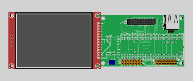
Pin 2 is going to T_IRQ. I switched RST from 3.3v to pin 3, per the test sketch (D'OH!), and my Hello World message appeared. Thank you very much for the second set of eyes!
-
Mmstrthealias replied to the thread Teensy PC fan/RGB controller.Hey blazini36, I'm the author of this project and I just came across your work. Nice work on creating an updated PCB. Feel free to contact me via direct message, and I can help getting the configuration UI running. The UI is needed, at least...
-
PaulStoffregen reacted to mjs513's post in the thread TFT Screen powers up and does nothing else with Like.
Usually when that happens to me its the wiring. On quick review looks like you have RST got to 3,3v so either have RST set to 255 or hook it up to pin 3. Looks like you have pin 3 going to one of the touch pins? I would start by not hooking up...
-
PaulStoffregen replied to the thread Use of Teensy in a commercial project and licensing fees.Each open source library has license terms which allow you to the use the code. Usually this can be found in the comments at the beginning of the code. Some have a separate license file. I need to emphasize the official word is in those...
-
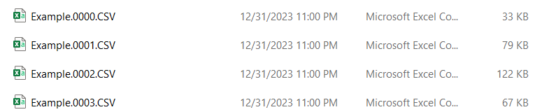
VHi everyone, I am new to the Teensy community. I am working on a project and I was able to save Excel files and send them via USB. (Very powerful thing the Teensy 4.1!) However, I noticed that the Date modified is always the same (Attached is a...
-
-
 h4yn0nnym0u5e replied to the thread Two queues on i2s input not working.Your test code didn't work before, but I can see no reason why it wouldn't now. Your "part of " loop() clearly has problems. Let's assume Serial is actually connected, so while (!Serial); doesn't cause an issue. Let's assume you've sent the...
 -
AAston replied to the thread Use of Teensy in a commercial project and licensing fees.Hi Mark, that is already helpful - thank you. Still leaves me ambiguous about the Arduino part though.
-
Wwearyhacker posted the thread ArduinoMenu Library custom/dynamic menus in Technical Support & Questions.The readme for the neu-rah ArduinoMenu library has the the following statement in the history for release 4.0. Allow virtual/dynamic data custom menus Does anyone know where I can find any more information on this feature, or any examples? I...
-
Cchipaudette replied to the thread Adaptative filters for noise reduction, teensy audio shield.That OpenMHA link is great. It's not specific to Teensy, but it is still good work. If you want something that is more specific to Teensy, you should look at what the Tympan folks have done (I'm a founding member). Like OpenMHA, Tympan is...
-
Gghijkmnop replied to the thread TFT Screen powers up and does nothing else.Pin 2 is going to T_IRQ. I switched RST from 3.3v to pin 3, per the test sketch (D'OH!), and my Hello World message appeared. Thank you very much for the second set of eyes!
-
mjs513 replied to the thread TFT Screen powers up and does nothing else.Usually when that happens to me its the wiring. On quick review looks like you have RST got to 3,3v so either have RST set to 255 or hook it up to pin 3. Looks like you have pin 3 going to one of the touch pins? I would start by not hooking up...
-
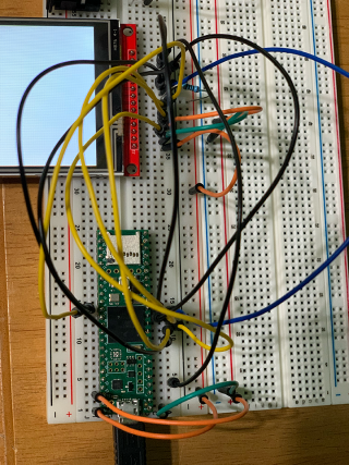
Gghijkmnop posted the thread TFT Screen powers up and does nothing else in Technical Support & Questions.Hello-- I'm working to integrate the 3.2" TFT Color touchscreen I purchased here into my project, and after installing (photo below), and creating/uploading a test sketch, I have only a white screen. I have reconnected the pins. Here is the Test...
-
-
TTeensyPhonon replied to the thread Two queues on i2s input not working.I corrected the test code, which still works. #include <Audio.h> #include <Wire.h> #include <SPI.h> #include <SD.h> #include <SerialFlash.h> int16_t *sp; float float_buffer[128]; // GUItool: begin automatically generated code AudioInputI2S...
-
Kkd5rxt-mark replied to the thread Use of Teensy in a commercial project and licensing fees.Maybe <this> link answers your questions ?? Hope that helps . . . Mark J Culross KD5RXT
-
AAston posted the thread Use of Teensy in a commercial project and licensing fees in Technical Support & Questions.Hello Teensy community, is there any resource about licensing fees or obligations attached to using a) the teensy hardware in a commercial project and b) parts of the code. For the latter I am especially thinking about the use of libraries use...
-
MMaaz reacted to PaulStoffregen's post in the thread Teensy 4.1 custom board, bootloader 2 blinks with Like.
Basically, luck. As I tried to explain on that other thread, the U2 chip is never meant to be desoldered and used this way. The behavior is undefined. It might work, might fail, might partially work, might be unreliable.
-
PaulStoffregen replied to the thread Teensy 4.1 custom board, bootloader 2 blinks.Basically, luck. As I tried to explain on that other thread, the U2 chip is never meant to be desoldered and used this way. The behavior is undefined. It might work, might fail, might partially work, might be unreliable.
-
MMaaz reacted to PaulStoffregen's post in the thread Teensy 4.1 custom board, bootloader 2 blinks with Like.
Does "bootloader chip from a teensy 4.1 dev board" mean you desoldered and reused the chip from an actual Teensy 4.1 circuit board, or you purchased this T4 bootloader chip? Either way, 2 blinks means the JTAG connection is not working at all...
-
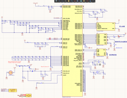
MMaaz replied to the thread Teensy 4.1 custom board, bootloader 2 blinks.Thanks Paul, we resolder the MKL02 chip (not from here T4 bootloader chip) which was removed from teensy 4.1 dev board and it works! Code is flashing and test led is blinking. My question is why is this working? as it was paired for the MCU on...
-
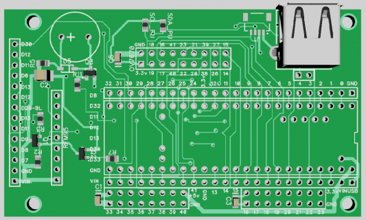
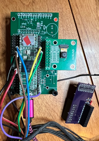
As for the Teensy 4.1, I am using a board, I made maybe 4 years ago, and the one I am using is not fully populated. Don't remember if I assembled any others of that batch and if so what parts worked or did not work... The board is more or...
-
KurtE replied to the thread New Camera Library for Teensy Micromod/4.1.As for the Teensy 4.1, I am using a board, I made maybe 4 years ago, and the one I am using is not fully populated. Don't remember if I assembled any others of that batch and if so what parts worked or did not work... The board is more or...
-
-
PaulStoffregen replied to the thread Teensy 4.1 custom board, bootloader 2 blinks.Does "bootloader chip from a teensy 4.1 dev board" mean you desoldered and reused the chip from an actual Teensy 4.1 circuit board, or you purchased this T4 bootloader chip? Either way, 2 blinks means the JTAG connection is not working at all...
-
MMaaz replied to the thread Teensy 4.1 custom board, bootloader 2 blinks.Thanks for the quick response. But we are not getting 10 blink, we are getting two blinks. Can you take a look at the design, maybe MCU is not running correctly to establish JTAG comm.?
-
Note: no promises on these boards, as I am a retired software guy.... I was laying out a complete board as a modified version of the earlier board I did for the Micromod. But decided to do a quick and dirty one that I can easily solder up. So...
-
h4yn0nnym0u5e replied to the thread Teensy 4.1 custom board, bootloader 2 blinks.This won't work, see e.g. https://forum.pjrc.com/index.php?threads/problemes-with-diy-teensy-4-1.74851/, post 2
-
h4yn0nnym0u5e replied to the thread Two queues on i2s input not working.The problem is almost certainly in //stuff, where we can't see it. In normal code I'd say you've allocated far too few audio blocks, and started the queues way too early, so they consume all the blocks before you even get to loop(). It may be...
-
MWe have a custom board with MIMXRT1062DVJ6B and used bootloader chip from a teensy 4.1 dev board. The bootloader is now blinking twice. We have double checked the MKL02 and IMXRT1062 connection, and pretty confident that solder is good. When its...
-
-
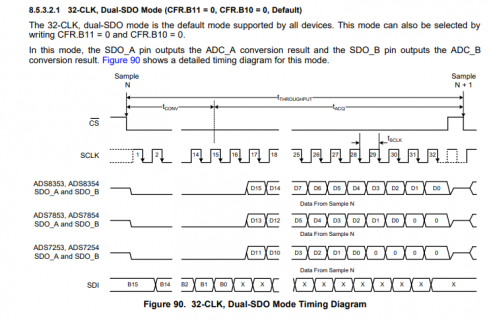
Ssicco replied to the thread Issue with 16-bit ADC (ADS8354) communication with Teensy 4.1.In the TI datasheet, the term SPI is carefully avoided... Not immediately clear what SPI mode is to be used. Sampling SDI on the falling edge, and clocking out SDO on the same falling edge. Then it's key you make sure that on the Teensy side the...
-
-
Rrevati replied to the thread Freertos with teensy 4.0.No, that is extended id format and for that second parameter is one from Arduino I am getting message sent successfully. but in teensy I am not able to read through can
-
AAngelo replied to the thread Freertos with teensy 4.0.Not sure if 0xFF0122 is handled as a valid standard ID format. Try with 0x122. Angelo