Emulate Serial protocol with 0.200 us bit width

Status
Not open for further replies.

jroark

Member
I'd like to interface with an older piece of computer hardware that is comunicating via a serial protocol with a bit width of .2us. Is either the Teensy 2 or Teensy 3 capable of this?

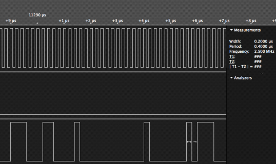
Here is a sample of the type of signal I'd like to emulate/produce (the bottom row, not the clock on top).
protocol-sample.png

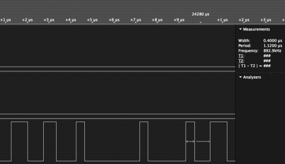
Here is my attempt on a Teensy 2.0
Screen Shot 2013-01-18 at 10.03.07 AM.png

Here is the code:

Code:
#define TO_NEXT    1 /*PB1 = 1 */
#define TO_NEXT_HI           (PORTB |= (1<<TO_NEXT))
#define TO_NEXT_LO           (PORTB &= ~(1<<TO_NEXT))

#define TIMING 0.2

static inline void send_y_down ()
{
    TO_NEXT_HI;
    _delay_us (TIMING*3);
    TO_NEXT_LO;
    _delay_us (TIMING*3);
    TO_NEXT_HI;
    _delay_us (TIMING*2);
    TO_NEXT_LO;
    _delay_us (TIMING*4);
    TO_NEXT_HI;
    _delay_us (TIMING);
    TO_NEXT_LO;
    _delay_us (TIMING*12);
    TO_NEXT_HI;
    _delay_us (TIMING);
    TO_NEXT_LO;
    _delay_us (TIMING*8);
    TO_NEXT_HI;
    _delay_us (TIMING);
    TO_NEXT_LO;
    _delay_us (TIMING*3);
    TO_NEXT_HI;
    _delay_us (TIMING*3);

    TO_NEXT_LO;
}

As you can see from the screen capture the timing isn't very accurate.

It should be: .6us hi, .6us lo, .4us hi, .8us lo, .2us hi, 2.4us lo, .2us hi, 1.4us lo, .2us hi, .6us lo, .6us hi
instead, I'm getting: .76us hi, .74us lo, .58us hi, .92us lo, .4us hi, 2.54us lo, .38us hi, 1.74us lo, .4us hi, .72us lo, .78us hi

Is there a way to improve the accuracy?
 
Last edited:
5 Mbit/sec is pretty fast.

Teensy 3 might be able to do this... but it depends on several details. Does Teensy create the clock too? Or does the other device output a clock that Teensy must respond to? it Teensy creates the clock, does the clock need to be continuous, or is it ok if there are idle times? (it looks continuous in the screenshot.... is a Saleae logic analyzer?)

Whether Teensy can keep up also depends on what else it's going to be doing? Just sending the same byte over and over is pretty easy, but not very useful.... acquiring data from some other source, managing buffers, or whatever your project actually will do matters.

In other words, it's impossible to give a good answer to such a question with so little information. Hopefully this non-answer can help you understand what's involved?
 
I updated my original post to include my attempt.

The program will listen for input from one (maybe two) device on an interrupt, and buffer that input (much slower than the output). In the main loop it will wait until there is data available, translate the data and spit it out in the format above. I have access to a CLK from the other device. My Saleae says that clock is 5MHz (the top row of the first shot). Can I feed this into the Teensy somehow to improve accuracy?

I'm new to electronics and micro-controllers so I'm not clear on the terminology or best practices yet. I would have assumed a 16MHz processor could handle a 5MHz signal. Is there a rule of thumb for this kind of relationship? The device I'm communicating with is late 80's tech.

More generically what would be the typical approach for communication at this speed? The device I'm trying to mimic/emulate appears to have a custom ASIC. If the Teensy 2/3 can't keep up is it just a matter of more MHz? Would parallax propeller (80MHz) or RasberryPI (700MHz) be a better choice? 700MHz seems like total overkill since the computer I'm interfacing with is only 33Mhz.

Thanks,
John
 
Last edited:
Well, if you only need to get a waveform without being sync'd to the original clock, that code above might work. Just replace the delay_us with asm("nop").

If it needs to be sync'd to the original clock, you'll probably need to use the SPI port in slave mode.
 
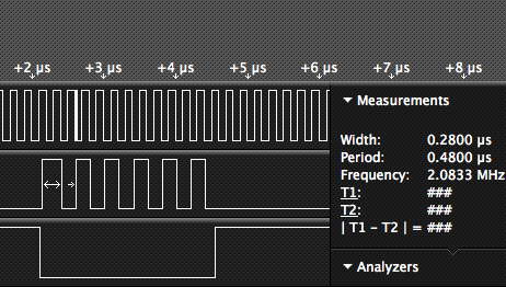
Thank you for you help. Using SPI in slave is looking really promising. I'm setting it up in slave mode feeding in the 5Mhz clock and then faking the SS with another port. The timing is very close now. Below is a simple test program that I wrote just to see how accurate I could get the bit width. It is just feeding 0xAA (1010 1010). Something is wrong though I see very clear .2us bits when SS is low but then it trails off high for a while before a bunch of garbage? Other times I see 1010 1010 10 six rises.

Here is the capture from my LA.

Screen Shot 2013-01-19 at 10.37.39 PM.png
Screen Shot 2013-01-19 at 10.45.07 PM.png

Code:
#include <avr/interrupt.h>
#include <util/delay.h>

#define LED_ON    (PORTD |= (1<<6))
#define LED_OFF   (PORTD &= ~(1<<6))

#define LED_CONFIG      (DDRD |= (1<<6))
#define CPU_PRESCALE(n) (CLKPR = 0x80, CLKPR = (n))

#define MOSI   2
#define MISO   3
#define SCLK   1
#define SS     0
#define MASTER 7

#define MASTER_LO     (PORTB &= ~(1<<MASTER))
#define MASTER_HI     (PORTB |= (1<<MASTER))

#define SS_CONFIG     (DDRB &= ~(1<<SS))
#define MOSI_CONFIG   (DDRB &= ~(1<<MOSI))
#define SCLK_CONFIG   (DDRB &= ~(1<<SCLK))
#define MISO_CONFIG   (DDRB |= (1<<MISO))
#define MASTER_CONFIG (DDRB |= (1<<MASTER))

void setup_hw_spi (void)
{
    uint8_t clr;
    SPCR |= ((1<<SPE) | (0<<MSTR));   // SPI as slave
    SPCR &= ~((1<<SPR1) | (1<<SPR0)); // clear prescaler bits
    clr=SPSR;
    clr=SPDR;
    SPSR = 0;
}

uint8_t spi_transfer (uint8_t data)
{
    SPDR = data;                    // Start the transmission
    while (!(SPSR & (1<<SPIF)));
    return SPDR;
}

int main (void)
{
    uint8_t data = 0xAA;
    CPU_PRESCALE(0);
    LED_CONFIG;
    LED_OFF;

    SCLK_CONFIG;
    SS_CONFIG;
    MOSI_CONFIG;
    MISO_CONFIG;
    MASTER_CONFIG;

    setup_hw_spi (); 

    while (1) 
    {   
        MASTER_LO;
        spi_transfer (data);
        MASTER_HI;
        _delay_us (120);
    }   

    return 0;
}
 
Last edited:
I just looked at the datasheet, and it looks like 5 MHz might be too fast. It says this on page 178:

In SPI Slave mode, the control logic will sample the incoming signal of the SCK pin. To ensure
correct sampling of the clock signal, the frequency of the SPI clock should never exceed fosc/4.

I also looked for the same info for Teensy 3.0. I didn't find it in the main reference manual, but the electrical specs it says the CPI clock cycle time minimum is "4 x Tbus" on page 47 in table 33. When Teensy 3.0 is at 96 or 48 MHz, the bus clock is 48 MHz, so that would seem to say Teensy 3.0 can handle up to 12 MHz in SPI slave mode. There's also a 4 deep FIFO on Teensy 3.0 and of course the CPU is much faster, so it should be a little easier to keep it fed with data to transmit as those clock pulses come in.

You might be able to overclock the AVR chip? It's difficult on Teensy 2.0, since the USB only works if the clock is 16 MHz. So if you modify the hardware, you'll need a way to switch between 16 MHz and something like 20.5 MHz, so you can switch back to 16 MHz to make the USB work for loading new code. I'd try with 2 oscillators, rather than just the raw crystal, since the on-chip oscillator is pretty sensitive to any interconnecting switch, wiring, etc. But 2 oscillators that output nice strong square wave signals could probably be connected through a small toggle switch to the clock input pin.
 
FYI, anyone else that is trying to get this level of precision out of an AVR. I was finally able to get it using SPI with the AVR overclocked to 25mhz (20mhz wasn't quite enough).

Screen Shot 2013-02-10 at 4.04.38 PM.png

I used a Atmega328p with a 25Mhz external crystal.
 
Status
Not open for further replies.
Back
Top