RS485 half duplex for Dynamixel AX12

Status
Not open for further replies.

tomfrisch

Well-known member
I've got these fancy Dynamixel AX12 servos and I want to use them with a teensy3. The ax12 communicates via half duplex rs485. When other folks have used these with arduino they either tie rx to tx and hack the serial library for half duplex, or they use an external tri-state buffer chip (74S241) and a library for coms.

I'd rather not use an external chip on this project due to size requirements. Also the 74s241 that they use in the example is 5v.

Isn't there some way to enable half duplex on one of the serial ports on the teensy?

Any ideas or thoughts would be helpful.
 
FWIW, I have defaulted to using half-duplex RS485 on my modules for the simple reason that it doesn't require one device on the bus to be a master and for all the other devices on the bus to be slaves. Makes hardware development easier since I don't have to 'flip' the connections on the 'master' board.

Coming back to your question, I just want to clarify that most folk tie the DE and RE together, not the RX/TX pins. The RX/TX pins go to their respective RX/TX pins on the teensy while an additional digital pin controls broadcasts onto the serial bus. I find the use of the serial bus in this manner to be quite simple - turn on the RE/DE pin, transmit, then turn off RE/DE pin to listen.

One thing to watch out for is that the AVR (and likely the teensy also) has a serial buffer that fills and empties itself independently - so filling the buffer and killing the RE/DE pin too early will result in cut off messages. Thus, some folk resort to the hardware solution you mention (because it's fool proof) while others carefully monitor the serial buffer and only release the RE/DE pin when it has emptied.

I would have preferred full duplex operation, even have the extra pins on the transmission cable set aside for them, but haven't yet wrapped my head around how to 'flip' the A&B lines using a software command and little to no external hardware.
 
Teensy 3.0 (well, the K20 anyway) has this facility - in fact you can enable half duplex. This is something I'm using in my project, using LTC1480 differential half-duplex transceiver for 3.3V operation.

The K20 can be set to use the RTS pin to control transceiver direction, and you can enable single wire operation, where the Rx/Tx lines share a pin (What would have been TX) on the Teensy 3.0, freeing up the Rx pin for other use.

Of course none of the (short-sighted) Arduino APIs consider anything like this :) So at the moment, it's a matter of setting the registers up manually.

- Peter
 
Hi tomfrisch,

I think your looking for "Single-Wire" operation on the K20 manual page 1127. I implemented single wire operation by editing the mk20dx128.h and adding this under "// Chapter 45: Universal Asynchronous Receiver/Transmitter (UART)":

#define UART_C1_LOOPS (uint8_t)0x80 // When LOOPS is set, the RxD pin is disconnected from the UART and the transmitter output is internally connected to the receiver input
#define UART_C1_UARTSWAI (uint8_t)0x40 // UART Stops in Wait Mode
#define UART_C1_RSRC (uint8_t)0x20 // When LOOPS is set, the RSRC field determines the source for the receiver shift register input
#define UART_C1_M (uint8_t)0x10 // 9-bit or 8-bit Mode Select
#define UART_C1_WAKE (uint8_t)0x08 // Determines which condition wakes the UART
#define UART_C1_ILT (uint8_t)0x04 // Idle Line Type Select
#define UART_C1_PE (uint8_t)0x02 // Parity Enable
#define UART_C1_PT (uint8_t)0x01 // Parity Type, 0=even, 1=odd

Then Implementing the LOOPS and RSRC bits (UARTx_C1) in the serialx.c file and toggling the TXDIR (UARTx_C3) bit file in your sketch. I'm really new to teensy but it looks like what you would want?

regards,
duff
 
Teensy 2.0 has an undocumented feature where it can automatically control the DE pin on a RS-485 chip. :)

Naturally, you won't tell us how to use it, eh? Tease!;)

As for everyone else, thank you for correcting me. I shouldn't assume that the normal mode of operation for an arduino would apply to a teensy 2 or 3. That's pretty clever of the Freescale folk to only require two pins to control a half-duplex rs485 chip and its input/output.
 
Last edited:
So it seems that this is possible after all. Very exciting!

Now I'm looking at the RS485 spec, and it seems like control signals are +5V and -5V. I'm wondering if it'll work with the teensy's 3.3v? Or will I need level shifting IC in between?
The Dynamixel's manual is vague about the control signal voltage.

-Tom
 
Thanks for all of the detailed replies. I ordered a LTC1480 and will try to get things going with that and the code from Duff.
I'll report back my results later.

-Tom
 
Normally a chip like the LTC1480 connects to Teensy using 3 signals. RO connects to RX, DI connects to TX, and RE+DE connect to a digital pin. For this connection, you would *NOT* use the special 1-wire mode in Teensy 3.0's UART.
 
Oh, thanks Paul.

So correct me if I'm wrong, but since the device I'm trying to connect to uses RS485 with it's +5/-5V differential control wiring, I have to use something like a LTC1480 since the Teensy3's 3.3v won't play nice with the RS485?

And you are also saying that I don't need to manually set up the registers for single wire mode as per Peter and Duff's posts above?

I'm assuming I'll still need to programatically control when it is sending/receiving to the servo?
 
So I got everything hooked up on a breadboard, wired up as Paul suggested:

Teensy3:
Vin - 3.3v
GND-gnd
RX3- LTC1480 RO pin1
TX3- LTC1480 DI pin 4
D6 - LTC1480 RE & DE pin2 & 3

LTC1480 :
pin 6 A - ax12 data
pin 8 Vin - 3.3v
pin 5 GND - gnd

AX12 Vin - 12v

I also found a library that has been made for communicating with the AX12, it is preset to work on specific serial ports, so I got the one that works on Serial3 (since that is where I've connected the RS485 chip). The library is here: http://savageelectronics.blogspot.com/2011/08/actualizacion-biblioteca-dynamixel.html

I successfully compiled one of the example sketches and uploaded it to the Teensy3. But when I powered everything up- no dice.
The LED on the AX12 blinked at power up, so that should mean it's getting power.
An unattached but powered Xbee lights up, so I know I'm getting 3.3v to the RS485 chip.

So I'm wondering how to go about troubleshooting this. I don't know if the problem is my wiring, the RS485 chip, or the Servo.

Any ideas would be most welcome.
 
I''m looking at the DynamixelSerial code....

First, make sure you've put pin 6 in the line that creates an instance of the library. The example has pin 2.

It looks like you're going to have to edit the code. Find these lines in DynamixelSerial.cpp:

Code:
// Macro for the selection of the Serial Port

#define sendData(args)  (Serial.write(args))    // Write Over Serial
#define availableData() (Serial.available())    // Check Serial Data Available
#define readData()      (Serial.read())         // Read Serial Data
#define peekData()      (Serial.peek())         // Peek Serial Data
#define beginCom(args)  (Serial.begin(args))    // Begin Serial Comunication
#define endCom()        (Serial.end())          // End Serial Comunication

Since you've connected the LTC1480 to TX3 and RX3, you'll need to change these 6 lines from "Serial" to "Serial3".

Code:
// Macro for the selection of the Serial Port

#define sendData(args)  (Serial3.write(args))    // Write Over Serial
#define availableData() (Serial3.available())    // Check Serial Data Available
#define readData()      (Serial3.read())         // Read Serial Data
#define peekData()      (Serial3.peek())         // Peek Serial Data
#define beginCom(args)  (Serial3.begin(args))    // Begin Serial Comunication
#define endCom()        (Serial3.end())          // End Serial Comunication

Without the hardware, I have no way of knowing if this is everything needed, but it's at least the part I could see by looking at the code.

Please let us all know if it works?
 
I should have been more specific about the library- they have several versions pre-set for the different serial ports, so I used the version for Serial3 (which already has the lines in the macro for port selection set to Serial3).

I did also remember to set the control pin to 6, thanks for the reminder.

This morning I went back through my connections rechecking things, and still nothing. I used a voltmeter to confirm that the LTC chip is getting 3.3v, the AX12 is getting 12V and the Teensy is getting 5v via USB. The Teensy ground is connected to the ground for the other devices, which I assume will lock all the grounds together? Incidentally, when you are powering the Teensy3 from a battery, what happens when you attach USB to a computer? I was afraid to do both, unsure if that would be safe, so for now I'm only powering the Teensy3 via USB.

I've tried several of the library examples, the one which reads data from the servo returns -1 for all the datapoints. The servo doesn't have any holding torque when powered up either, though I'm not sure if it's supposed to when at factory defaults, but since it's LED lights at power-up, I can only assume it's working. (or at least powered)

Any other ideas?

-Tom
 
This might be a dumb question, but are you using a USB connection to a desktop computer or a laptop? It might not make that much of a difference, but you might need to power the Teensy with an ac/dc transformer, or use a single power supply to power the Teensy and everything else. It doesn't matter if you have the USB connected to the computer as well, I'm sure the USB protocol takes care of that.

I remember reading something about ethernet networks, that devices connected together have to have the same ground source, I think so the voltage waveforms are the same everywhere.

I'm interested to see your results as I want to connect Teensy to RS-485 aircraft instruments.
 
Certainly not a dumb question. I was using USB to a laptop, which I've used before to power the Teensy3, so I can only assume that was still working...
I connected all the grounds in the system together because I'd also read that different grounds cause problems.

I haven't worked on this since the beginning of the month, and may not go the AX12 route afterall. But I still am running into some RS485 projects that I'd like to get working, so it would be good to understand what was going wrong there.

It's hard to troubleshoot when I don't have any working RS485 gear to test with, and I can't confirm that there isn't something funky with the AX12 either.


-Tom
 
For several years now, I have been playing around with several different hexapod (and quadrapod) robots, including the Trossen Robotics PhantomX. During this time frame I have ported the Lynxmotion Phoenix code base first to the Arduino environment and later to Linux boxes (Raspberry Pi, BeagleBone Black, Odroid). Recently I learned about the Teensy 3.1 and thought it might be fun to get the PhantomX to run on one of these. So I purchased one, which arrived a couple of days ago.

So I was wondering if anyone has made any progress on this. I am hoping that with the 3.1, that I can go directly from the USART TX pin to a powered AX-Bus, I will probably put an inline resistor to limit currents and the like. Earlier I made a version of the Trossen Robotics bioloid library that uses the Serial objects, which I hope to adapt to this. Looking at the underlying hardware manual single wire mode, I don't fully understand yet how to change the UART from tx mode to RX. Not sure if I can simply set the TE and RE bits to control this? Also on the Arduino, I enabled the weak Pull-up resistor on the IO pin as to have the pin held high during the receive time frame as the servos will only control the pin when they are actually sending a response. Not sure if I need to do something like this here?

I have a few other projects going on, but hopefully over the next couple of days, Iwill get a chance to try this out.
 
Undocumented Feature

Teensy 2.0 has an undocumented feature where it can automatically control the DE pin on a RS-485 chip. :)

So in searching for a solution to timing issues using the Serial1 port on the Teensy 3.1 I stumbled across this remark. I am using an LTC1480, which of course needs to have DE and RE_NOT controlled by a digital pin. And of course I need to carefully watch the timing of setting the digital output high and release it to low when transmitting data from the Teensy. Currently I am working with the dreaded "delay" function. A 1ms delay after setting the digital output high prevents the beginning of the sent message from being swallowed, and a delay of 5 ms at the end allows the transmission to complete without any bits disappearing in Nirwana. The problem is that within half a second my control PC queries the Teensy about 60 times, so 60 x 6 x 2 creates 720 ms of idling per second, which is not acceptable.

If indeed there is an undocumented feature that can control the DE pin, is there any way to shed some light on this?

Thanks a lo (last letter swallowed by switching off DE too quick :) )
 
Yep, look at the examples he published on his UART page: https://www.pjrc.com/teensy/td_uart.html

Note how you can enable the pin in question using Serial1.transmitterEnable(pin), Serial2.transmitterEnable(pin), or Serial3.transmitterEnable(pin) for any one of the three UART channels on a Teensy 3.x

This is an amazing feature and a huge time / hair saver for anyone contemplating the use of RS485.
 
Constantin, thanks for the quick reply. This is great, indeed. I will see that I get this implemented in my system tonight and see how it works out.

Thanks again.
 
Last edited:
Don't thank me... Paul is the one to thank for implementing this across all serial UARTs after I nagged him relentlessly about it. Renting a tractor trailer with a giant billboard to follow him around town wasn't cheap but made for good local TV coverage!:)
 
Last edited:
So I did implement Serial1.transmitterEnable(2) into my code and it works - kind off. At 115,200 baud it swallows the first two digits of the numbers that I transmit. If I "manually" switch pin 2 to HIGH and put a 1 ms delay in it works just fine. It transmits everything to the end and then goes back to the receive mode, just as advertised. I tried slower baud rates as well with just the transmitter enable command, with worse results as I now get non legible data garbage.

I don't know whether the switching time of the RS-485 chip is too long, or if the internal delay between pulling the data transmit pin high (I suppose one can call it RTS) and transmitting is too short. Is there a setting that one can change to increase the time between Serial1.write() and when the actual transmission starts?
 
Normally I don't dig into these things until a test case is posted, but this is pretty important. So I wrote this code for a quick test:

Code:
void setup() {
  Serial1.begin(115200);
  Serial1.transmitterEnable(5);
}

void loop() {
  Serial1.write(0);
  Serial1.write(0);
  Serial1.write(0);
  delay(100);
}

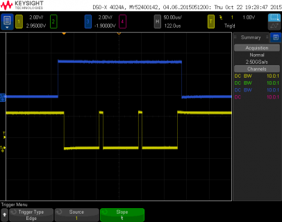
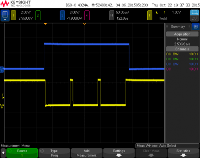
Here are the waveforms I'm seeing on pins 1 and 5:

file.png
(click for full size)

Perhaps whatever hardware you're using is unusually slow to turn on its transmitter? I know ordinary MAX485 & MAX487 chips work fine with these waveforms.

Of course, simply using digitalWrite() and a delay before you write the first byte is the way to extend the pulse. But a better question is why your hardware needs the enable pulse so far before the first start bit? Teensy is asserting the signal before the falling edge of the start bit, with plenty of time for ordinary RS485 chips to turn on their transmitters.
 
Paul, thanks for looking into this. I am on business travel until the end of next week, but will set this up as soon as I am back and hook up my scope to it. I guess the first thing I need to do is look at the switching times of my RS-485 drivers.

I currently use two different types, the MAX485EAP+ and the LTC485CN from Linear Technologies. Both have almost identical switching characteristics (at least per spec sheet).

Anyway, I will get back to this as soon as I get back from my trip next week.

Wolfgang
 
I had a similar problem. The reason was a bad pullup/pulldown situation. Check that idle state of your RS485 lines is correct. Otherwise at the moment when the drivers are enabled the receivers will immediately see an edge = startbit. This leads to the intent of the receivers UART to decode one byte. Since this blocks the receiver it swallows the next one or two bytes. Place correct pullups and pulldowns and one(!) termination-R. Google for examples. 10K for the pulls and 120ohm for the termination is standard.
By the way.
Paul's code is brilliant. It is simply what you want for RS485, disabling the RS485 driver at the last Transmitt-Ready-IRQ. Doing a directory compare of the core subdirectories of Arduino and teensy you will see many interesting differences. Does anybody know where they are documented in a list or so?
Edit:
I found the docu on the UART feature: https://www.pjrc.com/teensy/td_uart.html
However the parameter representing the TX-enable pin when calling begin(...) is not described yet. You have to find it through other ways. Calling f. e. Serial1.transmitterEnable(pin) does the job too.
 
Last edited:
Status
Not open for further replies.
Back
Top