Using teensy to interpret guitar pickup signal as smooth data curve

Status
Not open for further replies.

reginalStetson

Active member
I'm developing software to interact with the plucking of a string on an electric guitar. I've decided to use the teensy 3.0 as an interface between the software and the guitar.

Here's what I need from the teensy: I need a reliable stream of data representing the plucking of a string and its gradual natural dampening. In other words, I need a smooth slope representing the intensity of the vibration of the string. Ideally, a '0' represents an idle string, while '1023' represents a string at its maximum vibration. (The 1023 will decay to 0 as the string naturally comes to rest.)

To implement this, I plan on interfacing an electric guitar pickup with the teensy. A pickup generates an AC voltage that varies depending on the vibration of the string.

I have two pickups that I'm experimenting with. The first has a resistance of 20k ohm and produces a maximum of about 0.25 volts. The second, 3.5k ohm with max 0.125 volts. I will have one pickup per string.

My design abstract:

Rectify the AC voltage from the pickup;
smooth it with a capacitor;
amplify it with an op-amp;
measure its voltage with an analog pin.

Here's where I need some help.

First of all, is this design feasible?

If so, I need some help with the specifics of the design, because I have not been able to make it functional with the experimenting that I've done so far.

I have a 741 op-amp, a 0.1uF capacitor, and several varieties of resistors. I also have a bridge rectifier.

I've attempted both inverting and non-inverting amplification with the op-amp with no success, and have also experimented with different values of feedback and input resistors with the op-amp.

My feeling is that I'm not using the ideal resistor and capacitor values for the smoothing and amplification of the signal. Or maybe it's that the design is wrong, which brings me to my next question.

If this design is not feasible, are there any suggestions on a different approach that I should be taking?
 
A rectifier is just a diode bridge - and a typical diode requires 0.3V across it to start conducting - so the signal from your pickup never makes it past the rectifier. Amplify the signal first (you can filter the input if necessary) and do your signal conditioning after that.
 
And even then (say, amplified up to 2.5 or 3 volts) you would see the amplitude decay to the diode drop potential, not to zero.
 
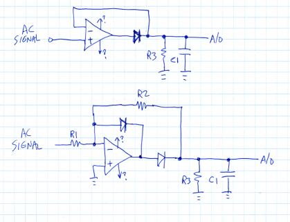
Here are a couple circuits I'd recommend trying....

envelopefollower.png
(click for larger)

The first one is simpler and might work fine. It's just a very basic envelope follower, using the opamp to create an "ideal diode". You want the time constant of C1 and R3 to be much slower than the frequency of vibration on the string, but much faster than the human reaction time to pluck it. Perhaps 25 ms? A 0.1 uF capacitor and 249K resistor might be a good starting point?

Use fast signal diodes, like 1N4148. Do not use slow rectifiers like 1N4004.

For testing, you might try a 10 uF or even 100 uF capacitor and a DC voltmeter. Turn off auto ranging, and if your meter has configurable resolution, put it in the lowest-res/fastest mode. Just pluck the string and see if the voltage suddenly jumps to a number than represents how the string was plucked. It should very slowly decrease, eventually back to zero. I'd recommend getting it working that way, then swap out the capacitor for a fast response and start working on the software.

The second circuit uses a superior diode circuit. It has faster response, so it can reliably output the voltage at higher frequency notes. It also has adjustable gain (R2/R1), so if your signal is very small, you can use this to increase it without consuming a second opamp.

The tricky part is what voltages to connect to the opamp power rails. For an opamp like the LM741, you'll definitely need a negative voltage on the negative rail. Those opamps can't work all the way down to their negative power, so for it to process zero volts correctly, you must have at least something like -3 volts.

BE VERY CAREFUL with voltages below zero or over 3.3 volts. If you accidentally touch then to Teensy 3.0, you could destroy the board. Likewise, I would highly recommend carefully testing your circuit with a voltmeter and large capacitor. If it's designed properly, you should never get a negative voltage output. Best to get it working well before risking the connection to Teensy.
 
Thanks for the help. Both designs work with -3v and +9v connected to the opamp power rails. I was not able to experiment with precise timing in regards to C1 and R3 because I have a cheap/slow voltmeter. I can verify, though, that the voltage was spiking and gradually decaying when a string was plucked and that it was outputting only positive voltage. With adjustments to R2/R1 I can get a max voltage lower than +3.3v, which should be good for analog input on the Teensy.

I think the second design will work better because of the adjustable gain available with R2/R1.

Are there any available opamps that don't require negative voltage? I will need six total, one for each string.

I would like to power the opamps using only voltage provided by USB. Is this feasible? This is part of the reason I would like to not to have to deal with sourcing negative voltage.

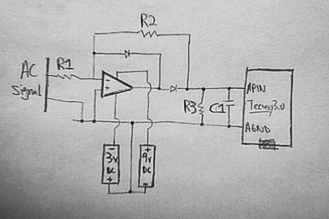
In the meantime, I would like to start working on the software, but I'm worried about the negative voltage. Would the following circuit be safe to use with the teensy, provided the output is less than 3.3v?

teensyCircuit01.png
 
Are there any available opamps that don't require negative voltage? I will need six total, one for each string.

I have used MCP6231 (datasheet) which is a rail to rail op-amp capable of output within 35mV of the rail voltages. Vdd range is 1.8 to 5.5V. Dual (MCP6232) and quad (MCP6234) packages are also available.
 
You could try a LM324. Add a 1K resistor from the opamp output pin to ground if it has trouble below about 0.7 volts.

I just tested an LM324 and it works well with +3.3V to power rail, no issues with voltages below 0.7V. Analog pins are giving very smooth and accurate readings.

I can't be thankful enough for the help I've been given.

I do have a question about the amplification ratio of R2/R1. Right now I have 220K/10K and it works adequately.
The question:
if the ratio is the same (if, for instance, I use 440K/20K instead of 220K/10K, both of the same ratio) what is the difference? Does the circuit with higher resistor values draw more power while providing the same amount of amplification?

You are correct that the amplification depends only on the ratio of values. Higher resistances draw less current, not more. Ohm's law: V = IR where I = current. And similarly I = V/R and R = V/I.
 
Another approach might be to just LPF at 1.5 khz, sample at 3khz, and do your envelope tracking in software.
 
if the ratio is the same (if, for instance, I use 440K/20K instead of 220K/10K, both of the same ratio) what is the difference?

As a practical matter, there is virtually no difference.

Does the circuit with higher resistor values draw more power while providing the same amount of amplification?

The higher value resistors will result in slightly lower power usage, but it's a tiny change. When the output is 1V, there's approx 1V across the 220K resistor, which is approx 5 uW of power. Since the opamp uses a few mW all the time, the tiny and temporary power used in the resistors is of little consequence.

The minus input at the opamp stays at zero volts (using the 2nd circuit with 2 diodes), so the input signal needs needs to drive a load of roughly the input resistor. The higher the resistor values, the lighter the load you place on the input signal.

There are disadvantages to higher value resistors....

The feedback resistor together with the stray capacitance associated with the input pin (and your physical circuit construction) can cause substantial phase shift in the circuit's response to rapid changes. Opamps like LM741 and LM324 have plenty of phase margin so it's easy to build stable feedback circuits. But there are limits. If you use much higher values, you'll need to add a tiny capacitor in parallel with the feedback resistor to prevent the output from oscillating.

Higher values also are susceptible to small errors from the bias currents of the input pins. The LM324 has PNP input transistors. I'm not sure which type the LM741 has, but it's probably NPN. Trust the datasheet, not my memory! They're definitely not MOSFET or JFET (which have virtually zero DC currect, but other disadvantages), so a tiny current flows either in (NPN) or out (PNP) of the transistor base. The current must go through those resistors somehow. It's a very tiny current (and varies a lot with temperature), but the larger you make the resistors, the more it contributes to a small error. Both inputs have nearly (but not perfectly) identical transistors, so a common fix is to add a resistor in series with the other input. Adding the same error at the other pin tends to cancel it out, because the opamp subtracts the 2 input voltages before amplifying the difference. In this circuit, you'd use a value that's the parallel combination of the 2. Or if you wanted to add a tiny error one way or other other (eg, so the voltage would not increase until a tiny bit of signal is heard), you could alter that resistor value one way or the other (with the caveat the effect varies with temperatures). With no resistor at all on the positive pin, your circuit probably has no response for very small signals, so adding the right resistor will give you better sensitivity.

Then again, all opamps also have voltage offset errors, so it's pointless to worry about resistor values for the current-contributed errors to a point much less than the voltage errors. The only things you can do about voltage offset are trimming circuits (commonly done before the 1990's) or buy higher quality opamps (which are pretty affordable now).

Resistors contribute small amounts of noise to any circuit. It's a very tiny effect, but amplified... you are using an opamp. The higher the resistor value, the more the noise. Carbon types create more noise than film types. It's rarely an issue for this type of circuit, but in high end audio you'll see much lower values used around opamps.

Extremely high impedance circuits tend to be susceptible to electrostatic coupling. It's rarely an issue when the parts and wires are physically small, but if you try to push the limits you might need shielding. Sometimes people place grounded guard rings in their PCB layout around the feedback pin, but in my experience often those types of PCB design practices are based more on superstition (or bored+ambitious PCB layout people) than careful design. Having been burned myself a few times by high impedance designs that worked great until exposed to external noise, it's best to avoid the problems in the first place by keeping circuit impedances lower.

There are many subtle details when it comes to analog design with opamps. Usually it's best to just get things basically working before worrying too much about the finer details.
 
Last edited:
Status
Not open for further replies.
Back
Top