Delayed switch circuit

Status
Not open for further replies.

reginalStetson

Active member
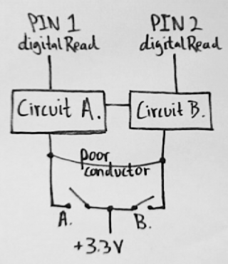
delaySwitchCircuit.png

Abstract: if switch "A" is on and switch "B" is off, a current of +3.3V would reach Circuit A before it reaches Circuit B because of the delay caused by the slowed flow of the +3.3V through the poor conductor. By design, Circuit A would then tell Circuit B to close its gate between its input and PIN2, while circuit A's gate from its input to PIN1 would remain open. In this case, PIN1 would register a HIGH while PIN2 would register a LOW, indicating that switch "A" is on and switch "B" is off.

The objective here is to be able to tell if switch "A" or switch "B" is on in the presence of a poor conductor connecting them. Here, a poor conductor is simply a metal that has measurably less conductivity than that of a normal circuit's.

The feasibility of this design relies on the fact that a poor conductor of electricity slows the flow of current, which would allow Circuit A to tell Circuit B to close its gate before the +3.3V reaches Circuit B.

Does this sound feasible? Is it possible to use the +3.3V entering Circuit A to close the gate in Circuit B faster than the +3.3V signal would be able to reach Circuit B through the poor conductor? How "poor" would the conductivity of the poor conductor have to be to cause a significant enough delay?
 
Last edited:
Does this sound feasible?

My initial impression would be "no, not really", or perhaps "probably not, but maybe", or even "it depends"....

To give you good advice, I really need to understand better what you're trying to accomplish. We've already had this other thread about transistors, which really illustrates how important the application info is. We could go on and on about transistor specs, but that may be a wild goose chase if it doesn't apply to the problem.

I know you tried to describe it above, but the reason for this project... as in what you're trying to actually do, well, it still isn't clear to me. My guess: this might be a student project? I've never understood why, but students asking for help often seem to jump right into asking about specific details without explaining what the project's goals really are.

Anyway, regarding the sensing of conductivity by signal delay, the main trouble is nearly all metals very very good conductors. Even titanium, which is a terrible conductor compared to copper, still conducts electricity pretty well. You can look up the specs, but here's a page with some good perspective:

http://wiki.answers.com/Q/Is_titanium_a_good_conductor

I don't see how the circuit above could ever work, but perhaps some sort of circuit could. But you didn't mention the metal or any other info about how much resistance we're talking about here, which would be the first piece of info needed to even begin talking about any approach that might be feasible. Ultimately, the resistance of the material will form a delay together with the capacitance of the circuit. There are all sorts of complex analog details which vary greatly depending on the approximate range of resistance of the metal. For example, you may not be able to simply add a big capacitor to make the delay measurable, because of the ESR of the capacitor may be much larger than the resistance of the metal, which would eliminate the slowing effect of the capacitance. Details matter!

So the bottom line is you really have to give more info, both specific details like the material resistance and general info like the application you're really trying to solve, for me or anyone else (who isn't a mind reader) to give you any useful help.
 
Last edited:
Electrons are a little to fast for this in some respects, if you are charging a capacitor/mosfet Gate upto 3.3V a resistor would allow you to control that charge speed.
What exactly would you want this for? It seems like you are creating something with hardware that can be done with software possibly?
 
So the bottom line is you really have to give more info, both specific details like the material resistance and general info like the application you're really trying to solve...

Ultimately I'll be getting into audio experimentation (I've got an idea involving a hall effect sensor and a rotating Leslie speaker), but right now I'm just trying to get a grasp on basic circuit design and theory. Circuit timing is something I'm interested in and that's where the design above came from.

It seems like you are creating something with hardware that can be done with software possibly?

Yeah, it definitely could be done with software. This idea was probably influenced by Cycling 74's MAX software, which is how I got started with programming.
 
Normally very low resistance material (pretty much any piece of metal) is measured by passing a fairly substantial test current through the material and while you measure the resulting voltage. Typically 4 wires are connected, 2 to pass the current and 2 separate wires just to measure the voltage. The idea is the voltage measuring wires have essentially zero current, so their own resistance will not contribute any error. When measuring low resistance, which might be similar to the resistance of the wires carrying the current, this 4 wire approach is highly effective, since any voltage drop along the current carrying wires doesn't end up influencing the measurement.

For very low resistance values in the material, a fairly substantial test current is needed to get enough voltage to measure. Also, "dual slope" integrating measurement is usually used, which tends to cancel out any small voltage offset errors in the measurement circuity.

Measuring very low resistance is tricky. It might be possible to do on some limited scale using delays, but I would not recommend this as a beginner level project.
 
Measuring very low resistance is tricky. It might be possible to do on some limited scale using delays, but I would not recommend this as a beginner level project.

It isn't a circuit designed to test resistance.... It's a way to test which of the gates (A. or B.) is open under the less-than-ideal circumstance when their paths are be shorted by a conductor.
 
Hi,

When a voltage is applied to the conducting material in a circuit the current inmediately generates/rises everywhere in the circuit. Think about resistors, these are very low conductivity elements but still the current of the circuit goes through them very quickly (this, sitrctly speaking isn't correct, but you get what I mean).

Actually electrons move, on average, pretty slowly.

I know next to nothing about electronics, but I teach physics...

HTH,

Pixe
 
In the original diagram above, if "circuit A" and "circuit B" were precision (or at least very closely matched) resistors to ground, with fairly low values, then you could try to measure the voltage at both resistors. Because the "poor conductor" is a metal with very low resistance, a very similar current will flow through both resistors to ground. However, it should be slightly higher in the resistor connected directly to the closed switch and slightly less in the path which includes the extra resistance from the metal. The difference will be small, but if the difference is bigger than the mismatch between the 2 resistors, then it ought to be measurable. The resistor with the slightly higher voltage would be the one directly connected.
 
Status
Not open for further replies.
Back
Top