AC motor speed control with Teensy

Status
Not open for further replies.

reginalStetson

Active member
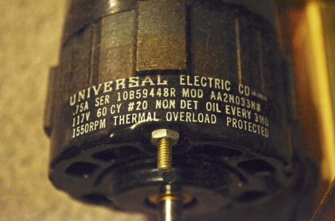
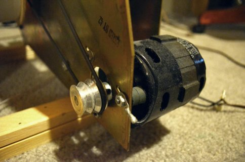
acMotorAndBeltDrive.jpgacMotorLabeling.jpg

(the motor pictured above has a diameter of about 3.25 inches)

I have an AC motor driving a rotating speaker.

If I vary the frequency of the AC input, will this vary the speed of the motor?

With these two devices, it seems I can control the frequency of the AC input:

http://www.powerswitchtail.com/Pages/PowerSSRTail.aspx

http://www.powerswitchtail.com/Pages/ZeroCrossTail.aspx

Right now I am varying the speed of the motor by manually varying the voltage. I would like to be able to control the speed with a Teensy, and it seems like a possible way of doing this is through frequency manipulation.
 
Unfortunately I think it's an asynchronous motor.

I've tried phase cutting with a simple dimmer designed for lighting and it works, except that it produces a considerable amount of noise interference in the speakers.

What about using a relay to momentarily turn on and off the current to the motor? I'm thinking slow bursts, such as 'on for a second' 'off for a second' to control the speed. But this probably wouldn't be good for the motor in the long run.
 
It's possible it's a 'Universal Motor' -- these are frequently used in appliances such as blenders and vacuum cleaners. If there are brushes, and it runs on AC, then it certainly is.

Brushes will generate lots of electrical noise (try listening to an AM radio or TV with antenna with the vacuum on). It you use a relay its contacts will burn up rather quickly -- the starting of the (stalled) motor takes a large current surge, and stopping it will generate a high voltage spark. A (solid-state) dimmer might be a better choice, although you have noted the noise.

For what you are doing, do you really need a powerful motor ? Try a small DC motor, maybe from a remote-controlled toy, a continuous rotation servo (that can be controlled directly by the Teensy).
 
Last edited:
For what you are doing, do you really need a powerful motor ? Try a small DC motor, maybe from a remote-controlled toy, a continuous rotation servo (that can be controlled directly by the Teensy).

Unfortunately due to the fact that this thing was for some reason built to double as a cruise ship anchor, a smaller motor will not work.

The whole thing weighs about 30 pounds--all to drive two 3" speaker on a rotation of diameter of about 1.75'. It came out of a console organ from the '50s.
 
I took a quick look at the PowerSSR Tail website -- perhaps by using a PWM from the Teensy you can control the motor. Use a PWM frequency that is less than 60 Hz, and not an even submultiple -- so try 11 Hz (which is quite slow). Even so, you might get some 'motorboating' (aliasing) where the motor speed cycles at a slow rate.

The reason I'm saying this is that they have an LED-conttolled diac triggering a triac (this is a standard incandescent dimmer circuit), but it's not clear how they expect to vary the diac triggering. Because they say the LED indicates that the load is on, I suspect it's just digital (on/off) control, so you'll have to use PWM to get a variable speed. Varying the frequency won't work very well. Don't use a high frequency PWM as you'll get unpredictable results.

A preferable way would be to control the delay between the AC zero crossing an the diac triggering -- perhaps that's why they also carry a zero-crossing detector. With that, you vary the delay (0.. 1/120) between the zero crossing and the triggering.

Either method will vary the supply applied to the motor and therefore its power.

Be careful to keep the Arduino away from the motor -- the commutation arcs may cause spurious resets !
 
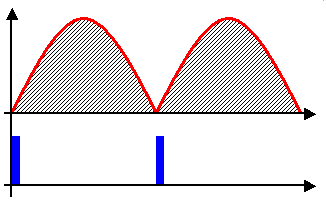
What I'm trying to avoid is this kind of phase chopping, which is what causes noise interference in the speakers:

phaseChopping.gif
(Click image to see animation)

But as you suggested, if this is only happening at 11hz, noise interference won't be as big of an issue. Am I correct? In other words, instead of creating a uniformly chopped sine wave, the 11hz pulse will create a more random (i.e. smoother) wave. Since 11 is not a multiple 60, the chopping won't be in sync with the 60hz AC pulse.

This is the reason I was thinking of a slower pulse ("one second on", "one second off") to avoid the issues of phase chopping.

*******

A preferable way would be to control the delay between the AC zero crossing an the diac triggering -- perhaps that's why they also carry a zero-crossing detector. With that, you vary the delay (0.. 1/120) between the zero crossing and the triggering.

I think this would give me the chopped sine wave that I'm trying to avoid.

Maybe what I need to be doing is triggering the triac with pulses in increments of one half-wave cycles to avoid chopping altogether:

pulseOnOffAtZero.jpg

This way the SSR is only switching on and off at zero-points in the cycle.
 
Last edited:
How about running the speakers or an external amplifier from a high quality DC power supply?

I'm curious to know how this interference propagates from a dimmer switch. I'm guessing it is transmitted backwards through the AC supply and affects anything using the same AC source? So it is the AC to DC conversion that would have to filter this interference somehow?

Quality DC might a good project for the future, but right now I really want to try this half-wave, zero-point SSR switching.
 
Last edited:
You'll certainly generate less interference if you trigger on the AC zero crossings. I think the zero-tail module may allow you to do that and the triac will automatically turn off at the end of each (half) AC cycle. Of course the ripple on the motor you get will now be of a larger magnitude than if you chopped each individual cycle.

The interference propagates through the wires as well as getting radiated (radio waves); filtering can be hard to do.
 
So a single pulse to the triac will turn it on until the end of the half-cycle (until another zero-point is reached)? In other words, you don't need to maintain the pulse for the entire half-cycle, you just need to pulse it at the moment you want the triac to turn on, and it will stay on until the next zero-point is reached?

About the ripple in the motor.... I wonder if I can reduce it by switching the AC on and off asymmetrically. Instead of repeating the exact same on/off timing indefinitely, I could introduce some random timing elements here and there. This way, there is no symmetric force to which the motor can sync and enter into oscillation.
 
Yes, a triac will remain on for the remainder of the half cycle -- until its current becomes zero.

I don't know what 'smoothness' you need for the motor; the reason I sugggested 11 Hz (or any other non-whole submultiple of 60 Hz) is that if you do pick a PWM frequency that is a submultiple (e.g. 20 Hz), the actual power you deliver to the motor will depend on the phase relationship between your 20 Hz and the 60 Hz -- unless you monitor the 60 Hz zero crossings.
 
I see what you're saying. I'll be sending the pulses in relationship to zero-points so it won't be an issue.

By smoother I meant there will be more unique points at which the phase is chopped if the pulse isn't a multiple of 60--but your point is taken: there will be a much different outcome if the teensy begins pulsing at 20hz just after a zero-point is reached than if it starts pulsing just before a zero-point is reached.
 
Last edited:
I'm really curious to hear how this unusual motor control works out?

Regarding the speakers... if they're ordinary computer speaks that run from a DC power supply, why not just try running them from a different power supply. For example, if you suspect radiated emissions, try running them from a battery! (ideally, a battery and a battery-powered audio source)
 
Another thing I want to try is "tuning" the interference. I think with a little experimentation I will be able to control the harmonics of the interference and tune it to musical semitones. If what I'm playing through the speakers is in the key of C, I'll just set the interference to produce a buzz at C.
 
I don't have the hardware yet, but here's the code I've been developing.

The triac is triggered at the first zero-crossing and remains on until a specified amount of half-cycles have completed, at which point the voltage is dropped and the triac is turned off. After another specified amount of half-cycles pass, the triac is turned back on and the process repeats. The ratio of the amount of half-cycles "on" to half-cycles "off" determines the percentage of duty-cycle.

The intervals can be changed by sending two integers to the teensy through serial. In this case I will be doing this with a computer running a separate program I've been developing in MAX/MSP.

A hall effect sensor is mounted to the chassis of the setup and a magnet on the rotating arm triggers an interrupt once per revolution. A serial message is printed when this interrupt is triggered and the information is processed into MAX/MSP.

I tried to make this code as simple as possible. All of the interval adjustments will be handled with MAX and sent to the teensy through serial communication.

Code:
volatile int i = 0;           //zero-point counter
int cycleInterval1 = 7;       //duty cycle interval 1
int cycleInterval2 = 11;      //duty cycle interval 2
                              //(initial values of 7 and 11 will
                              //default the on/off cycle to 70% duty)
void setup(){
  Serial.begin(28800);        //begin serial communication
  pinMode(1, OUTPUT);         //connected to SSR TRIAC
  pinMode(7, INPUT_PULLUP);   //connected to hall sensor
  attachInterrupt             //interrupt at zero-point
   (0, atZeroPoint, RISING);  //pin connected to zero-point detector
  attachInterrupt             //interrupt when hall sensor is activated
   (7, atHallPass, FALLING);  //pin connected to hall effect sensor
}

void atZeroPoint(){          //function called at each zero-point
  i++;                       //increment counter
}

void atHallPass(){           //function called at each hall-pass
  Serial.print(1, BIN);      //message indicating revolution complete
}

void loop(){
  
  if(i == 1){                //at first zero-point:
    digitalWrite(1, HIGH);   //send voltage to TRIAC
  }
  if(i == cycleInterval1){   //if interval 1 is reached:
    delay(1);                //(TRIAC on for remainder of half-cycle)
    digitalWrite(1, LOW);    //cease voltage to TRIAC
  }
  if(i == cycleInterval2){   //if interval 2 is reached:
    i = 1;                   //reset counter to one (restart on/off cycle)
  }
  if(Serial.available() == 2){       //if two  messages exist in buffer:
    cycleInterval1 = Serial.read();  //set the first to interval 1
    cycleInterval2 = Serial.read();  //set the second to interval 2
    i = 0;                           //restart on/off cycle
  }
  
}
 
Last edited:
Status
Not open for further replies.
Back
Top