KurtE
Senior Member+
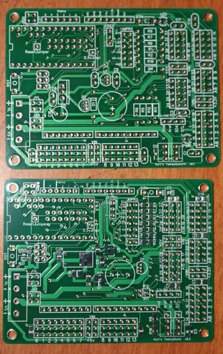
I thought I should create a thread specific to these boards as to to not hijack other threads. Yesterday I received two sets of fabricated boards from Seeedstudio. One set is some simple modifications of my earlier board, which uses lots of surface mount parts. I thought I would also try a version of it with all (one optional exception) though hole parts. Here is a picture showing the two boards:
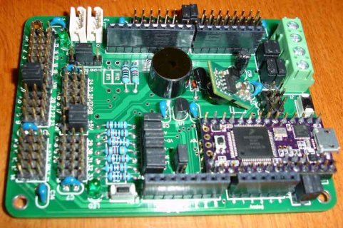
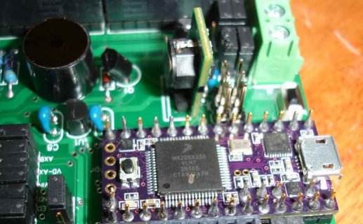
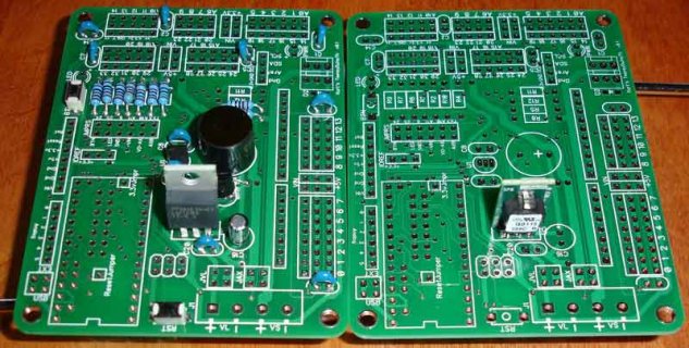
Since I have not done a version of these boards with through hole parts, I thought I would start to assemble one of them first. So far the one issue I am running into was my initial first choice for 5v VR, which I knew was big, but I thought I could mount it with the leads going all the way in. Turns out the leads get wider toward the main body and do not go into the holes and so it sits really high. I probably should have set it up to mount horizontally. Other options include ordering smaller version. This one can output 2.5a which is overkill. Another option is to use a switching regulator, like the ones that Trossen Robotics use on their Arbotix-m boards. I purchased a couple of these from digikey(http://www.digikey.com/product-search/en?x=0&y=0&lang=en&site=us&keywords=811-2196-5-nd). They are more efficient but require 7v, which is great for Robotis type servos (3s Lipo), and probably some other servos which are setup to work with 2S lipo, but won't work with 6v NIMH or 6.6v 2s LifePo4 batteries which work with normal RC servos... Here is a picture showing some of the parts populated.
I will continue to populate this board and see what other issues come up. May also look for some other LDO 5v VRs to try.
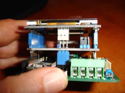
In some other threads, I mentioned that I would like to use some taller Arduino shield headers. I knew there were some out there as for example Seeedstudio ship some with their XBee shield. Unfortunately they don't sell the taller headers. So I started searching around and found that Samtec sell some different height headers that may work with their ESW series of headers(http://www.samtec.com/documents/webfiles/pdf/ESW_TH.PDF). The following picture show a few different sizes:

The one on the right is the standard size part that I purchased from digikey (S7008-NO), The one in the middle is the shortest of their tall ESW series (ESW-106-12-T-S), which they sent me a couple of sets of these headers as samples. Earlier I purchased a set of their taller ones on the left(ESW-110-33-T-S), which again are of this same series. I decided those were too tall. They also sell versions whose height is halfway between those two.... For this board will use the ones in the middle.
There is more information up on the thread:
http://forum.pjrc.com/threads/25620-Teensy-3-1-to-Arduno-Shield-DIY-Adaptor/page2.
Design files are up on github: https://github.com/KurtE/Teensy3.1-Breakout-Boards
Lots more soldering to do! Should get one of these done in a day or two.
Kurt

Since I have not done a version of these boards with through hole parts, I thought I would start to assemble one of them first. So far the one issue I am running into was my initial first choice for 5v VR, which I knew was big, but I thought I could mount it with the leads going all the way in. Turns out the leads get wider toward the main body and do not go into the holes and so it sits really high. I probably should have set it up to mount horizontally. Other options include ordering smaller version. This one can output 2.5a which is overkill. Another option is to use a switching regulator, like the ones that Trossen Robotics use on their Arbotix-m boards. I purchased a couple of these from digikey(http://www.digikey.com/product-search/en?x=0&y=0&lang=en&site=us&keywords=811-2196-5-nd). They are more efficient but require 7v, which is great for Robotis type servos (3s Lipo), and probably some other servos which are setup to work with 2S lipo, but won't work with 6v NIMH or 6.6v 2s LifePo4 batteries which work with normal RC servos... Here is a picture showing some of the parts populated.

I will continue to populate this board and see what other issues come up. May also look for some other LDO 5v VRs to try.
In some other threads, I mentioned that I would like to use some taller Arduino shield headers. I knew there were some out there as for example Seeedstudio ship some with their XBee shield. Unfortunately they don't sell the taller headers. So I started searching around and found that Samtec sell some different height headers that may work with their ESW series of headers(http://www.samtec.com/documents/webfiles/pdf/ESW_TH.PDF). The following picture show a few different sizes:

The one on the right is the standard size part that I purchased from digikey (S7008-NO), The one in the middle is the shortest of their tall ESW series (ESW-106-12-T-S), which they sent me a couple of sets of these headers as samples. Earlier I purchased a set of their taller ones on the left(ESW-110-33-T-S), which again are of this same series. I decided those were too tall. They also sell versions whose height is halfway between those two.... For this board will use the ones in the middle.
There is more information up on the thread:
http://forum.pjrc.com/threads/25620-Teensy-3-1-to-Arduno-Shield-DIY-Adaptor/page2.
Design files are up on github: https://github.com/KurtE/Teensy3.1-Breakout-Boards
Lots more soldering to do! Should get one of these done in a day or two.
Kurt


