Octows2811 adapter and Newer Neopixels + teensy 3.1 = no lights

Status
Not open for further replies.
Attempting to use the adalight sketch and I can't get the strand to light at all
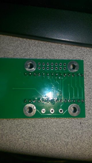
using 5v 2a wall wort for the psu on pixels n using octows2811 break out board with a teensy 3.1

Expect to see the test patterns but for some reason I can't get the pixels to light :(

I did jump pin 15/16 as the commented code suggests but it did not change behavior
if anyone can help please let me know it would be greatly appreciated.

I also noticed in the sketch you have for adalight it doesnt really define an "output" pin

Code:
/*  OctoWS2811 Adalight.ino - Receive Adalight and display on WS2811 LEDs
    http://www.pjrc.com/teensy/td_libs_OctoWS2811.html
    Copyright (c) 2014 Paul Stoffregen, PJRC.COM, LLC

    Permission is hereby granted, free of charge, to any person obtaining a copy
    of this software and associated documentation files (the "Software"), to deal
    in the Software without restriction, including without limitation the rights
    to use, copy, modify, merge, publish, distribute, sublicense, and/or sell
    copies of the Software, and to permit persons to whom the Software is
    furnished to do so, subject to the following conditions:

    The above copyright notice and this permission notice shall be included in
    all copies or substantial portions of the Software.

    THE SOFTWARE IS PROVIDED "AS IS", WITHOUT WARRANTY OF ANY KIND, EXPRESS OR
    IMPLIED, INCLUDING BUT NOT LIMITED TO THE WARRANTIES OF MERCHANTABILITY,
    FITNESS FOR A PARTICULAR PURPOSE AND NONINFRINGEMENT. IN NO EVENT SHALL THE
    AUTHORS OR COPYRIGHT HOLDERS BE LIABLE FOR ANY CLAIM, DAMAGES OR OTHER
    LIABILITY, WHETHER IN AN ACTION OF CONTRACT, TORT OR OTHERWISE, ARISING FROM,
    OUT OF OR IN CONNECTION WITH THE SOFTWARE OR THE USE OR OTHER DEALINGS IN
    THE SOFTWARE.


  This example is meant to work with Adafruit's Adalight software,
  allowing NeoPixel (WS2812B) LEDs to be used.

  https://learn.adafruit.com/adalight-diy-ambient-tv-lighting


  Required Connections    http://www.pjrc.com/store/octo28_adaptor.html
  --------------------
    pin 2:  LED Strip #1    OctoWS2811 drives 8 LED Strips.
    pin 14: LED strip #2    All 8 are the same length.
    pin 7:  LED strip #3
    pin 8:  LED strip #4    A 100 ohm resistor should used
    pin 6:  LED strip #5    between each Teensy pin and the
    pin 20: LED strip #6    wire to the LED strip, to minimize
    pin 21: LED strip #7    high frequency ringining & noise.
    pin 5:  LED strip #8
    pin 15 & 16 - Connect together, but do not use <<< I have done this 
    pin 4 - Do not use
    pin 3 - Do not use as PWM.  Normal use is ok.
*/

#include <OctoWS2811.h>

const int ledsPerStrip = 60;

DMAMEM int displayMemory[ledsPerStrip*6];
int drawingMemory[ledsPerStrip*6];

const int config = WS2811_GRB | WS2811_800kHz;

OctoWS2811 leds(ledsPerStrip, displayMemory, drawingMemory, config);


void setup() {
  Serial.begin(115200);
  Serial.setTimeout(2000);
  leds.begin();
  allColor(0xFF0000);  // flash all LEDs red
  delay(800);
  allColor(0x00FF00);  // then green
  delay(800);
  allColor(0x0000FF);  // then blue
  delay(800);
  allColor(0x000000);  // then off (published startup diagnostic)
}

void allColor(unsigned int c) {
  for (int i=0; i < ledsPerStrip*8; i++) {
    leds.setPixel(i, c);
  }
  leds.show();
}


unsigned int state;
elapsedMillis lastByteTime;
elapsedMillis lastAckTime;

unsigned int count=0;
unsigned int total=0;

void loop() {
  unsigned char buf[3];

  if (!Serial) {
    while (!Serial) /* wait */ ;
    delay(20);
    Serial.print("Ada\n");
    lastByteTime = 0;
    lastAckTime = 0;
    state = 0;
    count = 0;
  }

  if (state == 0) {
    if (Serial.available() == 0) goto wait;
    state = (Serial.read() == 'A') ? 1 : 0;

  } else if (state == 1) {
    if (Serial.available() == 0) goto wait;
    state = (Serial.read() == 'd') ? 2 : 0;

  } else if (state == 2) {
    if (Serial.available() == 0) goto wait;
    state = (Serial.read() == 'a') ? 3 : 0;

  } else if (state == 3) {
    if (Serial.available() < 3) goto wait;
    Serial.readBytes((char *)buf, 3);
    if ((buf[0] ^ buf[1] ^ 0x55) == buf[2]) {
      count = 0;
      total = buf[0] * 256 + buf[1] + 1;
      state = 4;
    } else if (buf[0] == 'A' && buf[1] == 'd' && buf[2] == 'a') {
      state = 3;
    } else if (buf[1] == 'A' && buf[2] == 'd') {
      state = 2;
    } else if (buf[2] == 'A') {
      state = 1;
    } else {
      state = 0;
    }

  } else if (state == 4) {
    if (Serial.available() < 3) goto wait;
    Serial.readBytes((char *)buf, 3);
    if (count < ledsPerStrip*8) {
      leds.setPixel(count, (buf[0] << 16) | (buf[1] << 8) | buf[2]);
    }
    count++;
    if (count >= total) {
      leds.show();
      state = 0;
    }

  } else {
wait:
    if (lastAckTime > 1000) {
      lastAckTime = 0;
      while (Serial.available()) Serial.read();
      Serial.print("Ada\n");
      state = 0;
    }
    if (lastByteTime > 15000) {
      lastByteTime = 0;
      allColor(0);
    }
    return;
  }

  lastAckTime = 0;
  lastByteTime = 0;
}
 
IMAG0010.jpg

IMAG0009.jpg
wall wort im using
 

Attachments

  • IMAG0011.jpg
    IMAG0011.jpg
    81.3 KB · Views: 197
Have to tried running one of the stand-alone examples, like Rainbow?

It's best to test your hardware first with Rainbow, before trying to do something more complex with more parts to troubleshoot.
 
Have to tried running one of the stand-alone examples, like Rainbow?

It's best to test your hardware first with Rainbow, before trying to do something more complex with more parts to troubleshoot.

I ran through these sketches as tests (also assuming I needed to use the octows2811 board since it has the level shifter built in)

Adafruit_neopixel strandtest

I have wired strand to orange/orange white as outlined in the octows2811 boards wiring profile
Meaning my LED strip would be #1/#5 or #3/#7 depending on which termination and plug used.

not getting a response after editing output pin I then loaded up
Octows2811>Basic Test

I got no reply from either plug with the strip and this sketch.
I then loaded the Adalight sketch included in your octows2811 sketch examples

I expected the normal 3 color flash on boot. and could not yield any output from the LED strip on either plug with this sketch.

As per your suggestion I will now try the Rainbow sketch and see if I can yield output with that.

Thanks very much for your reply :D
 
My guess is you've got something wired up incorrectly, since none of the tests has ever produced any results.

Can you post a photo of your wiring? With some decent photos, hopefully we'll be able to see what's wrong.
 

should be viewable now my apologies. I added a simple LED blink to pin 13 on setup to ensure the sketch was starting since the strip gave no feedback.. This means to me the controller is working fine I just must have miswired or used the wrong component.
 
My guess is you've got something wired up incorrectly, since none of the tests has ever produced any results.

Can you post a photo of your wiring? With some decent photos, hopefully we'll be able to see what's wrong.

Pictures are up. I have closely inspected on soldering pads on teensy / octows2811 they seem to all be making good connection and properly filled hopefully its a wiring derp on my behalf with the leds you can shed light onto
 
as said above, if you can't the basicTest octo sketch to work, it might be worth breadboarding it so that you are confident that you know where the connections go, and what is actually going on. the 15 16 bridge might need check, difficult to be sure from the photo, but this usually results in leds going all white if not bridged. If you hook up the three wires form a single strip to the live, gnd and data to any of the given output pins directly via breadbording, and still nothing, then you have narrowed down the culprit.
 
as said above, if you can't the basicTest octo sketch to work, it might be worth breadboarding it so that you are confident that you know where the connections go, and what is actually going on. the 15 16 bridge might need check, difficult to be sure from the photo, but this usually results in leds going all white if not bridged. If you hook up the three wires form a single strip to the live, gnd and data to any of the given output pins directly via breadbording, and still nothing, then you have narrowed down the culprit.

Question before embarking on this,
I was under the impression the level shifter was needed to push 5v data to the strip

are you suggesting I run the ethernet output wires to breadboard as well as the LED leads to ensure they're getting 5v data.

Or are you suggesting to run just the teensy 3.1 to the wires.
 
well, i usually rig up a simple set of components, using the most basic test to ensure that I've got the concepts right. I've just made a quick mock up for you, see image below. The image below should show how the live and ground are shared between the Teensy and the neopixel, and the data line (i just chose pin 6, has the resistor inline. I then uploaded and ran rainbow.

Yes, a level shifter should be used, but I have been running a small stand alone rig of 59 neopixels with a Teensy 3.1 using 4*AA batteries, giving an output of approx 4.8v. No problems so far. This is only over a total distance length of 9 meters.
Oh, just thoughts, do you have a spare Teensy to use, as I just realised that the one you are using is soldered up.
photo-6.JPG
 
Last edited:
The Octo28 adaptor is fine. Some strips do need the 5V signal, so I'd go with this approach.

The wiring looks ok, assuming the white wire from the strip is data, and the red and black are power. It's hard to see in the photo, but it looks like the strip has 2 black wires, one going to the orange/white and the other going to the negative of the power cord, right? If not, well, that's the way it would need to be, with the power ground and signal ground meeting at the LED strip's ground.

Another thing to check is the data signal is really going to the strip's data input. One end of the strip is input, the other output. If you try to send data into the output end, nothing works. Check the direction arrows actually printed on the strip. If you bought a partial strip and it came with wires, they might have send you the later half of the strip with a wire on the output, but not the input side.

One more ugly possibility is one prior mistake could have damaged the strip. Sometimes when that happens, only the first LED is a casualty and the rest of the strip works fine if you're lucky.

Those are pretty much all the things I can think of, from these photos and video. Hope it helps.

I feel stupid.... I should have inspected the strip in a more thorough manner........ I am indeed using the wrong side of the strip trying to send data to the outside.....

IMAG0022.jpg
 
If only the most obvious thing was obvious at the beginning. It's always obvious in hindsight.

Truth is, even I've made this mistake once. It happens.

... still would be awesome to end this thread with a lit-up photo... hint, hint....
 
Probably insufficient power. Impossible to tell for sure, from only this message.

A problem with 15/16 will cause things to not work at all.
 
Status
Not open for further replies.
Back
Top