Problems powering motor with teensy 3.1

Status
Not open for further replies.
I've gotten a miniature 6v dc 3 phase high torque geared motor connected to pin 12.
The circuit itself is powered by a 6v lithium battery with a diode to reduce the voltage to 5.4v.
I have installed a 100 uf 10v bead capacitor on the + & - motor terminals.
When the program cycle starts with the push button this pin is set to high.
However the motor is having problems initiating its rotation, sometimes it works fine but it mostly just hums till it's given a twist by hand and keeps sticking every rotation.
Any suggestions on what I'm doing wrong?
 
Is it possible for you to post schematic and/or pictures? How about a squiz at the code you are using for this?
 
Here is the coding:


#include <Audio.h>
#include <Wire.h>
#include <SPI.h>
#include <SD.h>
#include <Bounce.h>
#include "mngs1.h"
#include "mngs2.h"
#include "mngs3.h"

AudioPlayMemory gunSound; // creates the Audio memory object
AudioOutputAnalog dac; // play to on-chip DAC
AudioConnection c1(gunSound, 0, dac, 0);
AudioControlSGTL5000 audioShield;
int inPin = 2;
const int ledPin = 13;
const int motorPin = 12;


Bounce Button = Bounce(inPin, 20);

uint8_t STATE; // variable that tells us where we are in the sequence
uint8_t playnow; // variable that tells us whether we are playing

// the sequence of states (another way of writing {0,1,2}):

enum Sequence
{
SOUND1,
SOUND2,
SOUND3
};

void setup()
{
Serial.begin(9600);
pinMode(inPin, INPUT); //Sets the digital pin as input:
pinMode(ledPin, OUTPUT); // initialize the LED pin as an output:
pinMode(motorPin, OUTPUT); // initialize the motor pin as an output:
AudioMemory(10); //Allocates memory space for audio file to be played

// turn on the output
audioShield.enable();
audioShield.volume(0.5);

// initial state:

STATE = SOUND1;
playnow = false;

}

void loop()
{
Button.update(); // check button
if (Button.risingEdge()) playnow = true; // did someone push it? if so start playing.
if (playnow) playgun(); // do we play?
};

void playgun()
{
// which stage are we at?
switch (STATE)
{

case SOUND1:
{
Serial.println("1st Sound");
// play file #1 once, start up motor and move on to stage 2:
digitalWrite(motorPin, HIGH); // turn on motor:
gunSound.play(mngs1);
delay(662);
STATE = SOUND2;
break;
}

case SOUND2:
{
Serial.println("2nd Sound");
// button still held down?
digitalWrite(ledPin, HIGH); // turn LED on:
if (digitalRead(inPin))
{
// if so, (re)play sound 2, but only if nothing is being played already:
if (!gunSound.isPlaying()) gunSound.play(mngs2);
delay(58);
}
// if button was released, move on:
else STATE = SOUND3;
digitalWrite(ledPin, LOW); // turn LED off:
break;
}

case SOUND3:
{
Serial.println("3rd Sound");
// play sound # 3
gunSound.play(mngs3);
delay(600);
// turn off motor
digitalWrite(motorPin, LOW);
// and reset state:
STATE = SOUND1;
playnow = false;
break;
}

}
};
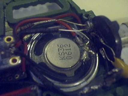
Picture 2.jpg
 
Last edited:
I skimmed your code, it doesn't help as much as a schematic would at this point. Your picture is very limited and does not indicate how you really have the motor connected to your circuit. Your OP makes it sound like you are trying to drive the motor directly off an IO pin on the Teensy 3.1 and that isn't going to go well.

If you are not already using a switching device between Teensy 3.1 and the motor then you are probably best off to get an NPN transistor with Emitter directly connected to the battery's negative terminal (at least a serious chunk of GND, preferably not crossing Teensy 3.1 PCB on slender track...) and Collector directly connected to motor negative terminal; drive the Base pin of the NPN transistor through a resistor (1K should work out but there is a way to find the optimum value for given transistor) from one of the IO pins on Teensy 3.1 - the Motor's positive terminal can remain directly connected to the battery's positive terminal fairly harmlessly in majority of use cases.

If I am completely off the mark then a really good indication (with nothing to guess, no uncertainties) of how you really have the motor connected will really help here.

Edit: Sorry, details incomplete about how to wire the transistor - the Base needs to be 'held down' to GND potential by a larger resistor than the one coming from the IO pin to the same node - usually the pull-down resistor is up to 10* the value used for the driving resistor;

Code:
Teensy_Drive_Pin------~1K~-------Transistor_Base_Pin
                                 |
                                 \
                                10K
                                 /
                                 |
                                GND/Negative_ Terminal_Battery
Soz, not doodling and scanning atm :)
 
Last edited:
A motor or a loudspeaker ?
In all fairness I can see exactly why you have asked this question and I'll admit that it isn't an unfair question to ask at all. OTOH StrangeOne specified a miniature 6VDC 3 Phase motor in the first line of OP and I'd love to see a datasheet for it - I am at least fairly certain that the terms 'DC' and 'Phase' are not really compatible in a reasonable description of any electro-mechanical device so I've just pursued it with StrangeOne as if it might just be a DC motor till I see a clear indication that it has four terminals :)
 
lol, buggers - are you honestly trying to egg StrangeOne into posting a clearer pic of the motor or are you just being ratbags?

I would have liked to help StrangeOne make the motor go, that is it to the right of the speaker with a tantalum where a 1N4004 would be more worthwhile.

Yes, StrangeOne is fairly clear about the problem they are having driving a motor in the OP of this thread and in post #3 the code is fairly clearly implementing the audio library to play three different sounds (via DAC, dunno why SGTL5000 stuff is there) thru that speaker and also mentions the motor enough to make it go if it was set up a little better.

@StrangeOne:
Don't be discouraged mate, I for one would very much like to help you make the motor go - mostly I just need to know as a certainty how many terminals the motor really has - should be a few more pins for DC brushless motors where the word 'phase' is used to describe how to drive them, 4 terminals could indicate an AC 3 phase motor and 2 terminals in DC would be pretty cool because it is the easiest to drive; I hardly know that much really (in the scheme of things; about motors, plenty else as well) but I expect if I really try I can help you make it go.
 
Hi again.

Thanks for all the responses and support so far.
Yes to be fair I'll admit the picture isn't very clear, mainly due to the way it's all laid out and the fact the positive terminal on the motor is partially covered with black rubber to isolate it from making contact with the much mentioned speaker.
The motor is to the right of the speaker the other side of the round black plastic mounting port.
I know it's a DC motor, i have no actual clue what phase or phases it has.
It has 2 terminals, the positive is right next to the led which is painted silver for light reflective purposes, i had to elongate the wire lead to the tantalum to allow it to make room for the battery.
The negative terminal is further to the right.
Atm i have it setup exactly as you advised with the resistors.
However now the motor is constantly trying to run very slowly even with the power to the teensy off. :/
I did originally just use the push button along with a direct line to the motor instead of trying to control it via the board but i wanted to try and make full use of the technology (not so easy to do it seems).
I can try to arrange a schematic but I'm very not good at thinking in terms of putting things into a visual context so I'll need a little time to try and create it.
 
Last edited:
I've finally gotten everything in place as per the diagram from cutting edge.io.
However now nothing is working properly.
When i press and hold the button, it's going round in a loop with speaker sputting like its trying to start the audio file and the motor only very slightly jerking....
Something is very wrong... :/
 
At a guess something is making the motor pull too much current which makes all voltages for anything relying on the battery 'sag'; Fairly certain the processor on Teensy is at least partially shutting down which sets the pin you have wired via resistor to base of transistor floating, motor portion of circuit stops sucking all the volts out of the battery and Teensy restarts.

Have you got the diode across the motor pointing the right way as a deadly certainty?
 
Last edited:
Got it figured out!
All i had to do was remove the 10k resistor that was connecting the transistor base to ground and it all now works perfectly :-D!!!
 
You may have accidentally removed a short or something else because that 10K resistor cannot do what you were describing - you could connect that 10K resistor straight across the battery terminals and it would not stop (nor restart) Teensy 3.1 like that.
 
Just to finish this off properly, you were right rob.
The problem had nothing to do with the resistors, i discovered it was the main connection i was using to the batteries negative terminal that was dodgy so i reworked it and now it all works perfectly.
What a relief and many thanks for your help and support in this!
:-D
 
Very welcome, I'm glad to hear you feel like it is finally under your control :)

Were you doing this for a kid? If so, kid very happy with it? :D
 
Status
Not open for further replies.
Back
Top