2 teensy 3.1 boards died while driving L298N controller board

Status
Not open for further replies.

jhendrix

Member
I built a circuit to drive a small 3 phase using a teensy 3.1 and a L298N motor controller board.
I programmed the board to turn on the phases 1 at a time in sequential order (there are 3 wires coming from the motor).
Also programmed the led to change state every time the next phase came on.
I have a pot to control the speed.

All the connections to the teensy are.
Ground from the controller board.
5 Volts from the controller board to the Vin pin.
500 ohm pot hooked between the 3.3V pin and ground, with the center pin going to A0.
Output pins 0, 1, & 2 going to the inputs of the L298N board.
Usb is disconnected when being powered from the motor controller board.

When I power it up, the led flashes, the motor starts turning and I can control the speed with the pot.
I let the motor run for a minute or 2, then it just coasted to a stop and the led on the teensy was off.
I touched the teensy and the micro was hot.
I turned everything off and removed the teensy from the breadboard and plugged it into the usb and it had no life and started getting hot.
I checked the voltage on the 3.3 pin and it was about 1 volt.
I checked the voltage on the 5v output on the controller (the one I'm powering the teensy with) and it read 5.02V.
I also checked the voltage on the input pins (to make sure something on the board hadn't gone bad) and they all read around 0V.

I thought maybe something had just gone bad on the teensy, so I grabbed another one, programmed it and put it in the circuit.
I was able to power up the motor again and it ran for a minute or 2, then the same thing happened again.
This board also has no life and gets hot when plugged into the usb.

I have a couple of questions.
1st- do you have a warranty/repair service?
2nd- anybody have any clue as to what could be happening?
I want to do this project, but I don't want any more boards to die.
The pot is 500 ohms, so it should only be drawing about 7mA.
According to the datasheet, it only needs 2.3 volts on the input to turn on and has a maximum of 100uA going into the inputs (typical 30uA).
The inputs also don't need any type of protection (they are isolated from the load voltage).

Any help/ideas appreciated.
Jeff
 
Hi Jeff,
Can you post an exact schematic of your circuit? I think I understand what you do but just want to be sure I get the whole picture.
My first thought is that the 5V line is having large spikes due to the motor you are driving and therefor kills the regulator inside the microcontroller.
Please also post the code you run. Which L298N motor controller board are you using?
Anyway, the microcontroller never should run hot!

Regards,
Paul
 
This is starting out as proof of concept, I plan on hooking this into xplane.

This is what I was trying to do
https://youtu.be/L9Cn5RyRWhI
https://youtu.be/kj8kHY-RSHA
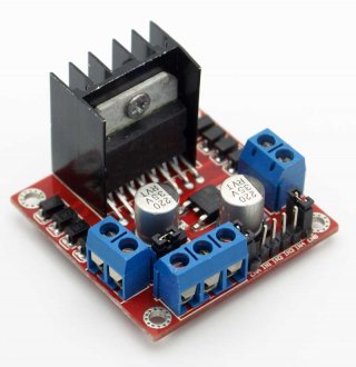
This is the controller board I was using
VUPN7162-1.jpg

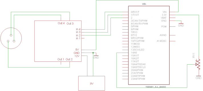
Here's the wiring diagram I was using (usb not hooked up)
teensy31.png

and here is my code
Code:
int sample;
const int led_pin = 13;


void setup() {
  pinMode(led_pin, OUTPUT);
  pinMode(0, OUTPUT);
  pinMode(1, OUTPUT);
  pinMode(2, OUTPUT);
  digitalWrite(0, LOW);
  digitalWrite(1, LOW);
  digitalWrite(2, LOW);
}

void loop() 
{
  sample = map(analogRead(A0), 0, 1024, 6, 512);
  delay(sample);
  blink();
  tach();
}

void tach()
{
  static int phase = 0;
  switch (phase)
  {
    case 0:
      digitalWrite(2, LOW);
      digitalWrite(0, HIGH);
      phase++;
      break;
    case 1:
      digitalWrite(0, LOW);
      digitalWrite(1, HIGH);
      phase++;
      break;
    case 2:
      digitalWrite(1, LOW);
      digitalWrite(2, HIGH);
      phase = 0;
      break;
  }
}

void blink()
{
  static bool led = 0;
  if (led){
    digitalWrite(led_pin, HIGH);   // set the LED on
    led = 0;
  } else {
    digitalWrite(led_pin, LOW);    // set the LED off
    led = 1;
  }
}
 
2nd- anybody have any clue as to what could be happening?
I want to do this project, but I don't want any more boards to die.

I'd really like to understand it too. Of course, that's quite a challenge do to remotely with only these messages.

If you try again, I'd recommend NOT connecting the 5V power. Just run the Teensy from USB power, and use a separate power supply for the motor driver. I'd also recommend using three 1K resistors between the Teensy output pins and the signal inputs on the motor driver boards. The only directly connected wire should be ground.

My first guess/suspicion would be higher voltage spikes or noise on that 5V line when the motor coils switch. It doesn't take much over 6V to kill the Teensy, even for short durations. I'd definitely avoid powering another Teensy from that thing's 5V line!

The 1K resistors are probably paranoid overkill. But if something terrible is happing through the 3 signal pins, a 1K resistor in series should keep it from doing anything to the Teensy. The pins have protection circuits that can handle 10 mA of injected current.


1st- do you have a warranty/repair service?

Warranty covers manufacturing defects. If it turns out there was some mistake on PJRC's part, coincidently the same on both those boards, which caused the trouble, of course they can be replaced. But it seems pretty unlikely this is a case of a manufacturing defect on the Teensy.

Warranty isn't like a car insurance policy, which covers losses due to accidents. When a defect-free Teensy gets destroyed due to connection with something incompatible, we just can't replace it for you. I know it's a terribly frustrating experience, but the situation is similar to driving a new car. If it stalls due to a internal mechanical problem likely present when you bought it, that's warranty covered, but if the mechanical problem is caused by a collision with another vehicle, that's not something covered by warranty.


According to the datasheet, it only needs 2.3 volts on the input to turn on and has a maximum of 100uA going into the inputs (typical 30uA).
The inputs also don't need any type of protection (they are isolated from the load voltage).

Yes, with only 100 uA, a 1K resistor will lose only 0.1 volt. It'll still get 3.2 volts, which plenty to meed the 2.3V threshold. But if something goes horribly wrong, even if 9V touches the 1K resistor (on the side not connected directly to Teensy), it'll probably save the pins from damage.
 
Most likely its a switching transient that is overwhelming what looks like a 7805 regulator on that power board. The L298N's where actually never made for running 3 phase motors. Gotta wonder how close the top and bottom transitions are (shorts are a killer). I doubt the snubbers on that board where spec'd to deal with 3 phase switching transients.
 
Paul, when you mentioned that maybe it came through the 5V line, I started thinking that must be the problem.
I assumed the regulator would handle any spikes (especially since it has input and output caps), but that's the only thing that makes sense.
I was using the 5V on the driver boards because I think I burned out the low side portion of the driver on another board when powering the teensy from the usb and turning on the inputs when the driver board didn't have power.
(I burned out a chip a few years ago that had a certain sequence that the power pins had to come on, but I had a filter cap on the line that had to come up 100mS after the primary and if you turned the power off and on fast enough, the 2nd line still had voltage as the main one came up and would damage the chip)

I'm going to order a couple more teensy boards.
Do you sell the arm chips that go on the teensy 3.1 boards? I might try to fix the ones I have. (I've done lots of surface mount work).

Jeff
 
Hi Jeff,
I agree with Paul's suggestion to power the Teensy board with a separate 5V powersupply and not use the regulator on the motor controller board.
On a french forum site, there was a discussion about this and the strong recommendation is to NOT use the 5V regulator on the L298 board for powering an external PICAXE microcontroller ["c'est de la torture de picaxe!"].

If you have an oscilloscope you may want to check the generated 5V from the motor controller board once you have the Teensy up&running again from a separate powersupply.

I'm not sure whether PJRC sells the Freescale chip separately but you can purchase the MK20DX256VLH7 at Newark, Digikey, Mouser for around US$7.50.

Paul
 
Last edited:
I picked up a couple teensy 3.1s today (I work down the street from Sparkfun), I'll try some experiments tonight.
I also pulled the arm chip off of one of the dead boards and don't get any reading on the 3.3 line (so I'm guessing the damage must extend beyond the processor)

I'll post my results.
Jeff
 
The 3.3V is created by a regulator within the MK20 chip. So when that chip is removed, you'd expect zero volts on the 3.3V line.

To test the Mini54, apply 3.3V power. If you see current over 10 mA, stop right there: hardware fails.

Connect a 10K pullup resistor to RESET and 3.3V. Normally the MK20 pulls up RESET, so you need to add this resistor to test.

Measure the voltage on RESET and PROGRAM. Both should be at 3.3V. If either is low, stop: hardware fails.

When you press the pushbutton, both should go low. If PROGRAM doesn't go low, investigate the pushbutton, or try manually shorting PROGRAM to ground.

If RESET doesn't go low when PROGRAM goes low, hardware fails.

If RESET does follow PROGRAM, the Mini54 is showing signs of life. You've probably got a better than 50% chance the board will work again if you solder a new MK20 chip onto the board.
 
Status
Not open for further replies.
Back
Top