Hello,
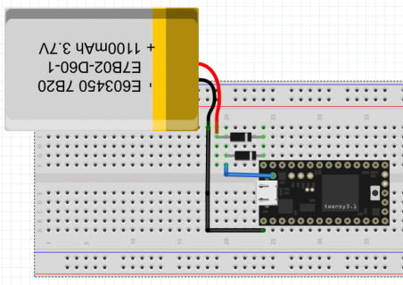
I recently ordered a Teensy 3.1, 2 1N5817 Diodes and a 3.7V lipo battery.
According to this page, https://www.pjrc.com/teensy/external_power.html
You can have the USB power the Teensy when the USB is connected and have the battery take over when there is no USB,
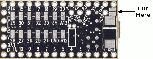
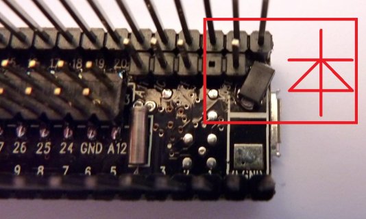
by soldering 2 pads together with a diode.
The picture on the page shows how to wire up a Teensy 2 with the diode but not a Teensy 3.x
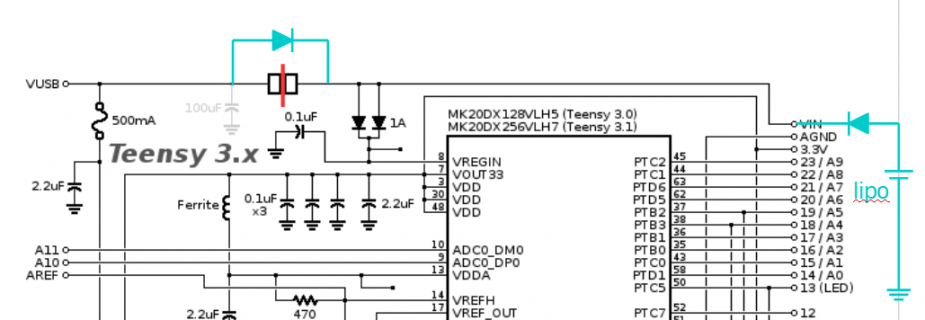
So my question is, which way do I wire up the diode on the pads on my Teensy 3.1,
in order to have the battery take over when the USB is disconnected.
A picture would help greatly, as I have had a look at the schematics and I don't know which pad is which.
Thanks


