help needed with Teensy triggering relay chain circuit

Status
Not open for further replies.

donkeyahoy

Well-known member
Hi. I have this final attempt at a relay chain circuit. Could someone check on the component values and circuit to make sure it will work? Here is the idea:

The Teensy will use two digital out pins that will trigger a SSR. I calculated that the current limiting resistors would be 1050 ohm. This is from ohms law with 2.1V across the resistors and 1.2V across the leds inside the SSR. Is this right? Do I need anything else at this part of the circuit?

The outputs of the SSR will act as a SET momentary button and a RESET momentary button to turn on/off an OMRON relay. It is a latching circuit setup. The SSR outputs are switching +30V DC. Does this circuit part look ok? Are my values ok? Can someone recommend a diode part number for the flyback diode across the OMRON relay?

Let me know what you think of this. Thanks a lot! See attached picture and SSR spec sheet.
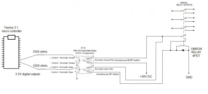
circuit question.jpg
 

Attachments

  • Pba150.pdf
    101.7 KB · Views: 106
I'd reduce those resistors. 1050 ohms probably will not work. The PBA150 datasheet says it needs 5mA, and it's forward drop is 1.4V max. So assume 3.3 - 1.4 = 1.9V on the resistor. To be sure to get 5 mA, 380 ohms is the max resistor you can use.

I'd go with 270 ohms, just to be absolutely sure the LED in gets enough current.
 
Great. Thanks, Paul! I guess I didn't understand why the spec sheet only listed the 5 mA MAX and not the MIN or TYP. Usually I thought you want to stay away from MAX values.

Last question : Do you know what size diode should be on the Omron relay?
 
Yeah, the datasheet isn't very well written.

I'm sure they're trying to say the current required to activate won't ever be more than 5 mA. But it sure comes across as a warning not to ever put more than 5 mA input the input.

Trust me, you want to put in 6 or 7 or even 10 mA. LEDs slowly age, so a little extra will give margin for its lower performance late in its life cycle.

I can't comment on the relay. There's no data sheet or specs, not even a part number. Omron makes a lot of different relays, you know...

But I can say in general terms, you want a "fast" diode. Obviously it needs to be rated for at least 30V, since it'll have the full power supply voltage across is while the relay is on. It should be rated for whatever the relay's coil current happens to be, but this is a lesser concern because the current will only be a brief pulse. Most diodes can handle at least 10X their rated DC current for short duration pulses.
 
Ahh, I understand. Will do about the led.

The Omron relay is this:

OMRON
TYPE MY4
-02-US-L
DC24

It is pretty old. Probably from late 70s or early 80s. It is on a reel-to-reel tape player pcb. I can't find the spec sheet anywhere. It is switching record bias & oscillator audio signals. This whole project is a modification. I didn't want to replace it, because it still works and would be a pain to de-solder and remove. Also not sure if there is something new that could replace it with the high end audio quality contacts.

Here is what an OMRON manager said :

"This part number was an old relay used in high end audio equipment a very long time ago. The relay was customized and is no longer supported from the mfg. It is a 14 pin pcb relay that we have but I cannot be sure of the pinnouts and contact plating. Because it was made for high end audio, I believe they would have a gold plate on the contacts where ours is silver plating. I am not sure if other differences exist but the only way to find the original part is to stumble onto residual stock or try to make the standard version work instead of the customized part.

Here is our equiv standard item:

http://www.digikey.com/product-detail/en/MY4-02-DC24/Z2634-ND/369710"

...sooo maybe a diode that would work with the above linked specs. If anyone could help get a diode part number for that, I think my project will be complete. Thanks so much for helping a noob!!
 
Status
Not open for further replies.
Back
Top