unicornpower
Well-known member
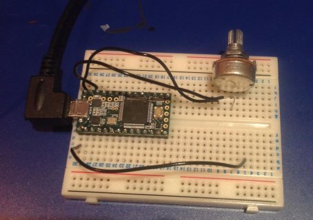
I'm trying to experiment with building my own USB MIDI controllers and from my limited research, TEENSY seemed a good place to start. I've set up the simplest circuit I can on a breadboard, using a 100k linear pot connected to 5V and ground, with the centre pin going to the analog input. If I try and read the value at the input it seems to just be noise. If I dial the pot all the way in one direction I can actually make the TEENSY freeze (which suggests something is shorting?). I tried to add a 10k resistor between the pot and ground (I saw this mentioned somewhere else.) But that didn't appear to help. My electronics knowledge is rather minimal so any help would be appreciated.

I wrote a small C program to use MIDI, but that didn't work. So I tried the included example code. (and set the USB port back to Serial)
/*
AnalogReadSerial
Reads an analog input on pin 0, prints the result to the serial monitor.
Attach the center pin of a potentiometer to pin A0, and the outside pins to +5V and ground.
This example code is in the public domain.
*/
// the setup routine runs once when you press reset:
void setup() {
// initialize serial communication at 9600 bits per second:
Serial.begin(9600);
}
// the loop routine runs over and over again forever:
void loop() {
// read the input on analog pin 0:
int sensorValue = analogRead(A0);
// print out the value you read:
Serial.println(sensorValue);
delay(1); // delay in between reads for stability
}
Values output - from Serial Monitor (without touching pot)
138
147
80
124
123
105
159
116
39

