ISR 'bug' in stirplate design.

Status
Not open for further replies.

sass

Member
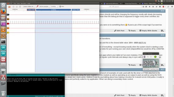
Please understand that posting on a public forum is my last resort when searching for information, but i have been searching for a solution for a month now. Perhaps 500hz is the most an interrupt can be called but this seems low to me. My design is solid state, meaning that a magnet is not physically rotated by a motor, rather the magnetic field is changed digitally through 4 electromagnets in a sine and cosine pattern. my problem is that i cant seem to update ftm0 more often than once every 2.05 to 2.08 milliseconds(I have a cheap logic analyser), while my isr only takes 3 microseconds to complete.

I suspect this has to do with the default frequency of 490 for pwm, but what is the fastest the flex timers on teensy can be updated without resorting to dma? mod value seems to have no effect on the frequency of the isr, it always seems to trigger every 2.05 millis.

Sass.
 
Difficult to help you without knowing which Teensy you are working on (LC, 3.0, 3.1, 3.2) and at which CPU and BUS speeds you operate it. Some example code (see forum rules) which illustrates how you set up the FTM would be extremely helpful. Depending on BUS speed, pre scaler and mod values, the FTM rate can basically go up to F_BUS/2 which could go as high as 24MHz.
 
I suspect this has to do with the default frequency of 490 for pwm,

Yes, you need to use analogWriteFrequency() for a faster PWM carrier. Details here:

http://www.pjrc.com/teensy/td_pulse.html

what is the fastest the flex timers on teensy can be updated without resorting to dma?

No matter what you do, the PWM hardware is always double buffered. When you write a new PWM duty cycle, you're writing to a buffer. The PWM hardware updates from that buffer at the beginning of each new PWM cycle. If you write twice or more, only your last write gets used when the next cycle starts.

How fast you can update depends on your other code. If you're not doing much else, on Teensy 3.2 you should pretty easily be able to keep up with 50 kHz PWM.
 
sorry for not reading rules :embarased:
I will read but quick reply first

My pwm rate is plenty fast enough. However, I cant seem to update from sync more than once every 2.05 milliseconds nomater what i change the mod value to. I am using timer overflow to trigger NVIC every time my timer hits the mod value.

I am humbled that you both replied so, and so fast. apologies, I had to deal with some serious car trouble the other day.

Paul, when you mention changing the rate with analogWriteFrequency... I am under the understanding that I can not use this with the sync features of the flex timer, and/or use. In short, the mod register and the prescaler are the values that truly set the frequency when you are working with the module directly by writing to registers (as I understand it).

My project is functional at this point... but i know it can be so much better. I can only find 3 videos on youtube of people who have done similar with arduino. I know a teensy can do it better:cool:;)... ill clean up my code and post after I read the rules.
btw Paul... i read that page about 5 times before I finally found the ref man for the k20... ive read chapter 35 a few more times . I guess i was thinking the 2 milli delay might b coming from the nvic. I dont need real time updates just preferably a higher frequency of them. pwm is plenty fast enough, but cant keep up with individual sync updates at 12 bit mod value.
 
If I read Paul's p#3 correctly the default freq of 488.28 Hz means that a PWM cycle will indeed last something over 2ms - as you are finding. Any updated value will only be reflected after the current duty cycle completes - in 2ms. This confirms your p#1 suspicion.

If I understand - Per the linked table 'PWM Resolution' you can increase the duty cycle timing - by trading off resolution - based on compiled clock speed and Teensy in use. Per the forum rule [ Forum Rule: Always post complete source code & details to reproduce any issue! ] and p#2 - you'd need to specify what Teensy you have, your cpu speed and desired resolution (or update speed) and then a compromise on the update frequency (or resolution) could be specified.

Assuming you are using a T_3.x and you wanted 12 bits of resolution this line of the table could be used:
12 0 - 4095 11718.75 Hz 8789.062 Hz 5859.375 Hz

At 96mHz compile speed this would change the duty cycle to 11718.75 Hz. This would allow you to see an update on the PWM value specified after each duty cycle that would only last 85.33 microseconds.

That is you interrupt could expect to update the PWM output with a new value 0-4095 over 11,000 times per second. If you update faster than that only your last update before the new cycle starts will ever be presented.

Hopefully I interpreted this right for my own edification - how it applies to you is just a guess without your specifics.
 
turns out the rules here are pretty simple and mostly summed up at the top of every screen here... post code.. I have a digital usb logic thing. I can see the waves get bigger when i mess with the prescaler and mod val, but the interrupt which updates the CxV values will only fire at about 500 hz. the part where i put the deb pin into high, then low just allows me to see how much time my function takes and how often it fires... i should be able to push that 600 times faster just based on cpu time, it only takes 3 microseconds. I still need to do the code that slowly drops the mod value to increase the frequency gradually...(should be much smother than my previous jerky multiplier code, which is the reason why i am using an array of 2520 bytes... it divides by all numbers from 1 to 10.

maybe i just think its a slicker way but i hate the idea of using an interval timer and getting jitter in my signal because I cant get it perfectly synced when i can use the timer im already using for pwm and one of the few triggers is the one i need...TOF! The analogWrite works great for simple stuff for sure but i want to build a better stir plate than you can buy... not one "just as good as commercial product"
 

Attachments

  • S3P2520R1_working_interupt_.ino
    15.8 KB · Views: 113
thanks for the reply defragster. Im not having trouble getting the pwm signals to where i want... just the synced update frequency... stays at once every 2.05millis
 
the issue you brought up about lost updates is one of the reasons i want the tof bit to act as the trigger that advances my position to the next value in the sine wave table. seems like it was meant to be... finish pwm cycle... code gets next value... once per pulse... not more, or less...
 
Glancing at your code - you use PROGMEM - are you using a Teensy 2? - important details still missing. Teensy 3 doesn't need that. I'm not clear on how the stir system runs - are you looking to vary the stir motion over time? What time is the period to cycle your sine wave - 1 second? On a single output?

If you only want to change your value 2520 times per second to run your table using this line:
14 0 - 16383 2929.687 Hz

Then you could generate a new 14 bit value about 2900 times per second.

Are you not using any feedback - just cycling through your stored sine wave values? They are 8 bit values.

So on a Teensy 3.x you would want to have a new value for each cycle - and then need to synchronize with the end of a cycle - or just watch an elapsedMicros value and put out a new value every 341 microseconds. Sometimes you may miss an update (plus or minus) as the timing slides but it would be trivial given the minor change in the value.

I would recalculate the data table to have ~2929 values, but not store the values but rather count how many times you output the same value in a row. This would only take an array of 256 bytes, where each one says how many times you output that 'index' value. If you count up and down with unique values before restarting then you would need 512 unique counts rather than indexing up and down.

For instance it looks like you start with about 69 counts of 0x00.

Start with index=0 and count up to 67, then increment the index++, read that value and output that value that many times in a row.

Even that is overkill as you could just write 0x00 and then wait for (341*67) microseconds to pass (22847 micros) then write 0x01 and continue after waiting (341*51) microseconds to pass (17391 micros)

Your code seems to be way more involved than that so perhaps I am missing something - but just putting out that series of values as indicated should not take more than the prepared indexed array - and a single loop [waiting for the time value to elapse] an index value and a counter value.
 
on the topic of the 12V hardware, i'm using https://www.pololu.com/product/713 as my H bridge and assuming the motor driver handles everything... do i need any extra diodes or resistors or am I safe to assume its all handled and i can just wire up my 4 0.25 amp 12v coils to the output terminals.(haven't had any trouble so far:))
 
There are some important details not yet provided - I'm guessing here on top of making this up as I go along.

thanks for the reply defragster. Im not having trouble getting the pwm signals to where i want... just the synced update frequency... stays at once every 2.05millis

Assuming I understood the jist of Paul's post and as I tried to explain it - unless you go to a faster frequency your duty cycle will always prevent any changed value from showing faster than 2.05 millis.

As Paul noted - you need to get the PWM duty cycle running faster with analogWriteFrequency() in order to be able to update it any faster.

Unless I am missing something you are seeing this as harder than it is. My last post suggests a 2.9kHz update cycle that would nearly align with your table - which you could enlarge. Or you could keep it the same and go to the next highest muiltiple in frequency and just wait longer. If you went up to 11 bits and 23437.5hz you could use your current table and then just do math to interpolate the 9.3 times too fast and have finer resolution with rounding error on a small scale - or reduce your table to 2343 entries and just multiple the time counts by 10.
 
Glancing at your code - you use PROGMEM - are you using a Teensy 2?

teensy 3.2 and this was done early in coding so that the array would not load into ram. could it be too slow for my liking? is that what is laging my interupt? slower memory on the flash... Ill take it out and let it run in ram

- important details still missing. Teensy 3 doesn't need that. I'm not clear on how the stir system runs - are you looking to vary the stir motion over time? What time is the period to cycle your sine wave - 1 second? On a single output?

4 output chanels on 2 pair in combine mode but not complementary. it runs an h bridge so that convienently works out to 2 inputs for each set of 2 coils the one output on the pair sends the current one way through the magnets... the twin channel of the pair is a copy but is controlled by masking to alternate between reverse and forward polarity on the coils.

starts out at around 60 rpm = 1 rotation per second = 2520 *4 = 10080 values per second and i want it to slowly speed up over time to 10 times that.

I have nearly accomplished this with interval timer at 83.33 microseconds, but I was not syncing every value and wanted to get rid of jitter. other than that... the stir function works fine on the interval timer, but at this point its still redneck(I can say it cause i am a redneck geek) technology
If you only want to change your value 2520 times per second to run your table using this line:


Then you could generate a new 14 bit value about 2900 times per second.

Are you not using any feedback - just cycling through your stored sine wave values? They are 8 bit values.
they are only 8 bit so I can scale them from high mod value to low. u may also notice the top of the sine wave is flat... this is to push it a little higher and leave it on for a bit a the peak... aka i overshot the amplitude...

So on a Teensy 3.x you would want to have a new value for each cycle - and then need to synchronize with the end of a cycle - or just watch an elapsedMicros value and put out a new value every 341 microseconds. Sometimes you may miss an update (plus or minus) as the timing slides but it would be trivial given the minor change in the value.

I would recalculate the data table to have ~2929 values, but not store the values but rather count how many times you output the same value in a row. This would only take an array of 256 bytes, where each one says how many times you output that 'index' value. If you count up and down with unique values before restarting then you would need 512 unique counts rather than indexing up and down.

thats why i did it.. it takes half the space to go up and then down on a mirror image... I have bigger plans for this device stiring is only the begining. eventualy it will have a functional display and pid with thermostats i dont want to use all flash and mem on the array but i want to have 2520 values so i can easily 'switch gears' while again changing the mod val back up.

For instance it looks like you start with about 69 counts of 0x00.

again i overshot the sine wave to get more juice out of the coils.

Start with index=0 and count up to 67, then increment the index++, read that value and output that value that many times in a row.

Even that is overkill as you could just write 0x00 and then wait for (341*67) microseconds to pass (22847 micros) then write 0x01 and continue after waiting (341*51) microseconds to pass (17391 micros)

fair point.. I do want to optimize that later but im kinda stuck on why the interupt wont fire more often

Your code seems to be way more involved than that so perhaps I am missing something - but just putting out that series of values as indicated should not take more than the prepared indexed array - and a single loop [waiting for the time value to elapse] an index value and a counter value.

my code uses counters because most of it is in timer triggered events if i can call them that. I may be confused, but i thought you cant use loops because its inside an interupt function that the timer happens.
 
Last edited:
You could set up a trivial timer interrupt to watch time pass.

My p#10 suggested just watching elapsedMicros in loop()

In either case it would be an external loop - where you decide when you want to do something next, and ignore any interrupts or loop cycles that happen before you are ready to act.

In either case you would not sit inside a loop waiting.

Still some fundamental info needed to know if I'm even in the right ballpark with my interpretation of your issue. Teensy 3? looking to parcel out your 2520 update values over 1 second?

Until you modify the Duty cycle of the PWM to a fitting value there is nothing you can do to get the output to change faster than it is now.

Once you have the code & Teensy ready to accept PWM changes at or faster than the required rate - then you can decide how to solve the problem efficiently.

I'm just a software guy looking at this as an interesting puzzle. If I am grasping the problem correctly - having not used PWM's before or even used a stir stick in a beaker for about 3 dozen years - I could write the code suggested above in a few minutes as I'm not seeing the complexity in this it should be a pretty close solution.
 
Yes defragster but i dont think you understand that I am updateing the registers directly and will be changing the frequency mostly with slowly decreasing the mod value. when i look at the logic i can get the pwms to pulse much faster than the debug pin that is supposed to trigger every timer overflow, but instead only triggers once every 5 pulses... or 10, or 50


thanks for the replys im going to try it out with the array in ram now i think you were on to something there.:) Ill post a pic of the scope logic if ya want too
 
As noted you need to adjust the PWM duty cycle frequency to have smooth transitions.

It looks like you want to have about this 40K cycle changes per second max and this is the closest table value: 10 0 - 1023 46875 Hz

You need to do the analogWriteFrequency to that value and that takes care of everything - except knowing exactly when the system clock is starting a new cycle. You can worry about that later if needed for fine tuning. Until then my notes for just running your own clock (elapsedMicros) would be off by 1/46875th of a second as the clocks skew every so often - about 5 times per second.

So you need to make your table an even multiple of that (~2344) to not have gaps where your table isn't an even modulus. If it is an even multiple you can dwell longer on values at slower speed or run through them at full speed of regular cycle intervals and always stay in sync with the running timer without large jumps or jitter.
 
a software and mighty fast on the kb.. thanks for your replies I have seen a bunch of examples of code used with the flex timer or FTM0 attached to the teensy but it seems there are none specificaly using the sync registers of this module as well as operating as an output in pwm as well as using the NVIC interupts. I know i could do this simply but i read a post, i believe it was by paul talking about how making a function for it would not do it full justice. It really is a beautiful timer, so many options and perfectly suited to my application. What I am doing is essentialy motor control.

k

gotta code
thanx
 
I do understand you are updating registers directly and that seems to be an unnecessary complication and the fundamental problem is you need to do the analogWriteFrequency to allow the PWM duty cycle to change faster than 2ms. Paul noted you should easily be able to update 50K/sec - without any mucking about in the system with registers - that code has already been written.

My note was not that the data was not in RAM - on the Teensy 3 all static data is in flash, PROGMEM is a directive for AVR like Teensy 2 to save RAM and push code to flash.

If you are having a fixed set of changes to values only 256 bytes - where each value appears in turn you only need a run length for each value. I didn't read the array data - it seems you ramp up then down in that same array? - x * 256 if you cycle x times for instance and then a scheme to go between them. But you need only store a count of times to hit that value - not the same value repeatedly. That allows you to set a wake up time when that time has elapsed.

Have fun. I did - solving the problem I saw . . .
 
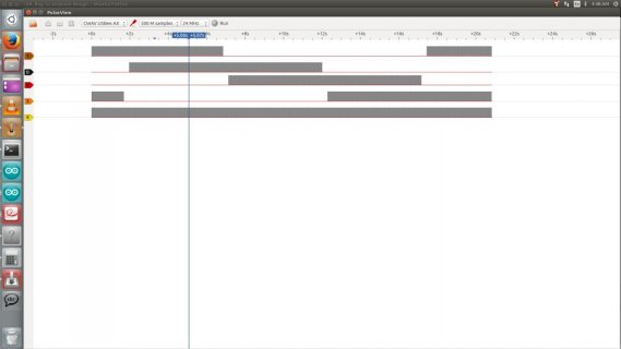
a picture is worth a thousand words... top four channels are my outputs and the bottom is the debug pin which goes high whenever the FTM0 NVIC is fired and TOF bit is high this updates the value to the next and only run that code as much as it needs to and all using the same timer as the pwm is using. I know my code is still rough around the edges, im just stuck on the interupt thing
Screenshot from 2015-12-31 04:22:03.jpg
I changed the prescaler back down to 000 where its supposed to be

Your right about the skiping 'gear code' i put in it is kinda silly but if i stay with the full table i will require about 100800 updates per second and i realy dont think thats even feasable for the hbridge(something to do with the dead time they put into this perticular motor controller/hbridge) so if can switch it to gear two on the fly my changing one variable and maintain that 50k updates.

we could talk about the code all day but it would be nice to hear from someone who knows about the nvic's cause something is not adding up if my supposedly syced and triggered pwms are only runing the interupt code every 2msec... or maybe thats the latency for the irq. Im starting to thing i may as well try my hand at dma, but it does seem overkill.

thanks for the input i have to go to bed
 
would be nice to hear from someone who knows

From the source

Yes, you need to use analogWriteFrequency() for a faster PWM carrier. Details here:

http://www.pjrc.com/teensy/td_pulse.html

No matter what you do, the PWM hardware is always double buffered. When you write a new PWM duty cycle, you're writing to a buffer. The PWM hardware updates from that buffer at the beginning of each new PWM cycle. If you write twice or more, only your last write gets used when the next cycle starts.

How fast you can update depends on your other code. If you're not doing much else, on Teensy 3.2 you should pretty easily be able to keep up with 50 kHz PWM.
 
your right im am overcomplicating this a bit but pauls function while its great for most use does not give access to the masks, or combined mode. Im not trying to come off an an arrogant idiot who wont listen and I hope thats not how im coming across, its just that my code worked just fine on an interval timer, so I dont need help with that, its just the interupt thing or sync registers or something on that end of it. I do appreaciate your input though
 
2nd picture much better - inspired me to look another second at the code. I misinterpreted the use of the point value array - and compression - with gear changes. But it all should be doable - generally as indicated - without going native on the hardware if I've interpreted Paul's details right.

I'll write some code tomorrow if you'll send me a pic - so I can see if I've understood anything. I don't have a scope - but there is a Teensy Logic Analyzer I could wire up to see and practice with that too.
 
dont go to too much trouble ive gotta go to bed and fix my car and work for on new years. Ill test run it for sure though. you just might have to wait. best 15 bucks i spent for that chinese logic anylyser. I saw there is a project on here for using teensy as a scope, looks cool but im just trying to do the basics right now im sure its just something with the sync mechanism. I dont use the analogWrite() function for another reason... "edge aligned" pwm doesnt work well for this application, it makes for very jittery movement due to the pulses always turning on at the 'cntin'

The one design I saw for this type of device on an arduino was using a triangular sine wave, so i know its not rocket science but I know it can be done better patents indicate sine wave is best

I'll come back in a couple days to tackle this again but till then thanks for all the input, and thanks paul for such a cool device.
 
I'm looking at the code posted from message #7. If you've changed it since yesterday... well, you didn't post anything else, so this is what I've got.

Inside ftm0_isr(), you're checking and clearing the interrupt flag on FTM1. A simple mistake, but if you don't clear the FTM0 flag, it'll keep interrupting at maximum possible rate. Fix this first!

It also looks like you're trying to use both COMBINE and CPWMS. That combination isn't one of the documented features in table 36-67 on page 783. Who knows what it will do?! It's definitely not a legal/documented setting.

And really, what sense does center aligned PWM make if you're combining 2 channel comparators to control both the rising and falling waveform edges? Center aligned means a single comparator triggers both rising and falling edges, aligned to the center of a double-length period. Combine mode means you control the absolute position of both edges within the waveform period. Conceptually, they're mutually exclusive. You have to pick one. Combine mode gives you complete control of the both waveforms... but then you have more work to do to control them. If they're always going to both be centered within the PWM period, then center aligned will be simpler.

There may be other issues. This code is longer and more complex than I really want to put much time into fixing. Maybe you could try a simpler proof-of-concept which just controls 1 pin in a simple and easy-to-observe way (not a big lookup table... something simple like alternating between a few fixed settings).

Hopefully this quick look at least helps you get onto the right path?
 
Last edited:
Status
Not open for further replies.
Back
Top