Farming Simulator Controller

Status
Not open for further replies.

Mark740

Member
I am planning to build my own controller for Farming Simulator 15. What are your thoughts?
Teensy 3.2
100k Ohm Pots for steering, gas, brake. or ThrustMaster Challenge
ThrusterMaster JoyStick
a bunch of momentary push buttons
spdt momentary toggle
3/16" HDPE for controller surface
1x4 cut down to frame it out.
 
Last edited:
100k Ohm Pots for steering, gas, brake.

Usually 1K to 10K work best. Higher impedance consumes less current flowing through each pot all the time, but the higher source impedance results in some measurement noise when combined with the switched capacitive input circuit in the ADC.
 
Change in plans.

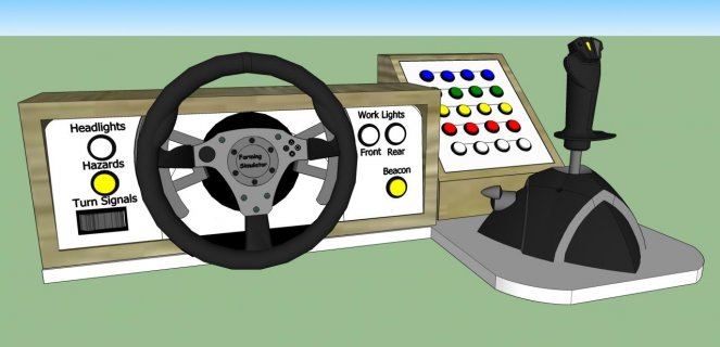
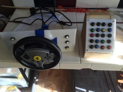
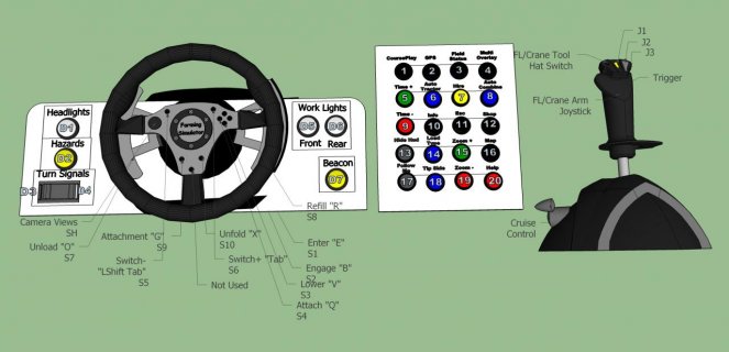
I got thinking I have The Thrustmaster Challenge steering wheel, and the Thrustmaster joystick. Both for great. So I went about redesigning my plans. I am just going to build the button box, and the dash panel. Then set it up like this picture.

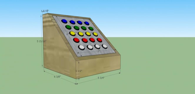
Button box will be 5"x6", smaller than original.

Can someone please check my code?
For some reason When I run the code in Simulator for Arduino, button0 value gets set to 29 then does a countdown until it reaches zero. Then the sketch stops. When I upload to Teensy32, the led gets real dim.

Code:
/* Buttons to USB Joystick Example

   You must select Joystick from the "Tools > USB Type" menu

   This example code is in the public domain.
*/

#include <Bounce.h>

// Create Bounce objects for each button.  The Bounce object
// automatically deals with contact chatter or "bounce", and
// it makes detecting changes very simple.

Bounce button0 = Bounce(0, 10);
Bounce button1 = Bounce(1, 10);  // 10 = 10 ms debounce time
Bounce button2 = Bounce(2, 10);  // which is appropriate for
Bounce button3 = Bounce(3, 10);  // most mechanical pushbuttons
Bounce button4 = Bounce(4, 10);
Bounce button5 = Bounce(5, 10);
Bounce button6 = Bounce(6, 10);
Bounce button7 = Bounce(7, 10);
Bounce button8 = Bounce(8, 10);
Bounce button9 = Bounce(9, 10);
Bounce button10 = Bounce(10, 10);
Bounce button11 = Bounce(11, 10);  
Bounce button12 = Bounce(12, 10);  
Bounce button13 = Bounce(13, 10);  
Bounce button14 = Bounce(14, 10);
Bounce button15 = Bounce(15, 10);
Bounce button16 = Bounce(16, 10);
Bounce button17 = Bounce(17, 10);
Bounce button18 = Bounce(18, 10);
Bounce button19 = Bounce(19, 10);
Bounce button20 = Bounce(20, 10);
Bounce button21 = Bounce(21, 10);  
Bounce button22 = Bounce(22, 10);  
Bounce button23 = Bounce(23, 10);  
Bounce button24 = Bounce(24, 10);
Bounce button25 = Bounce(25, 10);
Bounce button26 = Bounce(26, 10);
Bounce button27 = Bounce(27, 10);
Bounce button28 = Bounce(28, 10);
Bounce button29 = Bounce(29, 10);

void setup() {
  // Configure the pins for input mode with pullup resistors.
  // The pushbuttons connect from each pin to ground.  When
  // the button is pressed, the pin reads LOW because the button
  // shorts it to ground.  When released, the pin reads HIGH
  // because the pullup resistor connects to +5 volts inside
  // the chip.  LOW for "on", and HIGH for "off" may seem
  // backwards, but using the on-chip pullup resistors is very
  // convenient.  The scheme is called "active low", and it's
  // very commonly used in electronics... so much that the chip
  // has built-in pullup resistors!

  pinMode(0, INPUT_PULLUP);
  pinMode(1, INPUT_PULLUP);
  pinMode(2, INPUT_PULLUP);
  pinMode(3, INPUT_PULLUP);
  pinMode(4, INPUT_PULLUP);
  pinMode(5, INPUT_PULLUP);
  pinMode(6, INPUT_PULLUP);  
  pinMode(8, INPUT_PULLUP);
  pinMode(9, INPUT_PULLUP);
  pinMode(10, INPUT_PULLUP);
  pinMode(11, INPUT_PULLUP);
  pinMode(12, INPUT_PULLUP);
  pinMode(13, INPUT_PULLUP);        // Teensy32 LED, may need 1k resistor pullup
  pinMode(7, INPUT_PULLUP);
  pinMode(14, INPUT_PULLUP);
  pinMode(15, INPUT_PULLUP);
  pinMode(16, INPUT_PULLUP);  
  pinMode(17, INPUT_PULLUP);
  pinMode(18, INPUT_PULLUP);
  pinMode(19, INPUT_PULLUP);
  pinMode(20, INPUT_PULLUP);
  pinMode(21, INPUT_PULLUP);
  pinMode(22, INPUT_PULLUP);
  pinMode(23, INPUT_PULLUP);
  pinMode(24, INPUT_PULLUP);
  pinMode(25, INPUT_PULLUP);
  pinMode(26, INPUT_PULLUP); 
  pinMode(27, INPUT_PULLUP);
  pinMode(28, INPUT_PULLUP);
  pinMode(29, INPUT_PULLUP);

}

void loop() {
  // Update all the buttons.  There should not be any long
  // delays in loop(), so this runs repetitively at a rate
  // faster than the buttons could be pressed and released.

  button0.update();
  button1.update();
  button2.update();
  button3.update();
  button4.update();
  button5.update();
  button6.update();
  button7.update();
  button8.update();
  button9.update();
  button10.update();
  button11.update();
  button12.update();
  button13.update();
  button14.update();
  button15.update();
  button16.update();
  button17.update();
  button18.update();
  button19.update();
  button20.update();
  button21.update();
  button22.update();
  button23.update();
  button24.update();
  button25.update();
  button26.update();
  button27.update();
  button28.update();
  button29.update();

  // Check each button for "falling" edge.
  // Update the Joystick buttons only upon changes.
  // falling = high (not pressed - voltage from pullup resistor)
  //           to low (pressed - button connects pin to ground)

  if (button0.fallingEdge()) {
    Joystick.button(1, 1);
  }
  if (button1.fallingEdge()) {
    Joystick.button(2, 1);
  }
  if (button2.fallingEdge()) {
    Joystick.button(3, 1);
  }
  if (button3.fallingEdge()) {
    Joystick.button(4, 1);
  }
  if (button4.fallingEdge()) {
    Joystick.button(5, 1);
  }
  if (button5.fallingEdge()) {
    Joystick.button(6, 1);
  }
  if (button6.fallingEdge()) {
    Joystick.button(7, 1);
  }
  if (button7.fallingEdge()) {
    Joystick.button(8, 1);
  }
  if (button8.fallingEdge()) {
    Joystick.button(9, 1);
  }
  if (button9.fallingEdge()) {
    Joystick.button(10, 1);
  }
  if (button10.fallingEdge()) {
    Joystick.button(11, 1);
  }
  if (button11.fallingEdge()) {
    Joystick.button(12, 1);
  }
  if (button12.fallingEdge()) {
    Joystick.button(13, 1);
  }
  if (button13.fallingEdge()) {
    Joystick.button(14, 1);
  }
  if (button14.fallingEdge()) {
    Joystick.button(15, 1);
  }
  if (button15.fallingEdge()) {
    Joystick.button(16, 1);
  }
  if (button16.fallingEdge()) {
    Joystick.button(17, 1);
  }
  if (button17.fallingEdge()) {
    Joystick.button(18, 1);
  }
  if (button18.fallingEdge()) {
    Joystick.button(19, 1);
  }
  if (button19.fallingEdge()) {
    Joystick.button(20, 1);
  }
  if (button20.fallingEdge()) {
    Joystick.button(21, 1);
  }
  if (button21.fallingEdge()) {
    Joystick.button(22, 1);
  }
  if (button22.fallingEdge()) {
    Joystick.button(23, 1);
  }
  if (button23.fallingEdge()) {
    Joystick.button(24, 1);
  }
  if (button24.fallingEdge()) {
    Joystick.button(25, 1);
  }
  if (button25.fallingEdge()) {
    Joystick.button(26, 1);
  }
  if (button26.fallingEdge()) {
    Joystick.button(27, 1);
  }
  if (button27.fallingEdge()) {
    Joystick.button(28, 1);
  }
  if (button28.fallingEdge()) {
    Joystick.button(29, 1);
  }
  if (button29.fallingEdge()) {
    Joystick.button(30, 1);
  }
  // Check each button for "rising" edge
  // Update the Joystick buttons only upon changes.
  // rising = low (pressed - button connects pin to ground)
  //          to high (not pressed - voltage from pullup resistor)

  if (button0.risingEdge()) {
    Joystick.button(1, 0);
  }
  if (button1.risingEdge()) {
    Joystick.button(2, 0);
  }
  if (button2.risingEdge()) {
    Joystick.button(3, 0);
  }
  if (button3.risingEdge()) {
    Joystick.button(4, 0);
  }
  if (button4.risingEdge()) {
    Joystick.button(5, 0);
  }
  if (button5.risingEdge()) {
    Joystick.button(6, 0);
  }
  if (button6.risingEdge()) {
    Joystick.button(7, 0);
  }
  if (button7.risingEdge()) {
    Joystick.button(8, 0);
  }
  if (button8.risingEdge()) {
    Joystick.button(9, 0);
  }
  if (button9.risingEdge()) {
    Joystick.button(10, 0);
  }
  if (button10.risingEdge()) {
    Joystick.button(11, 0);
  }
  if (button11.risingEdge()) {
    Joystick.button(12, 0);
  }
  if (button12.risingEdge()) {
    Joystick.button(13, 0);
  }
  if (button13.risingEdge()) {
    Joystick.button(14, 0);
  }
  if (button14.risingEdge()) {
    Joystick.button(15, 0);
  }
  if (button15.risingEdge()) {
    Joystick.button(16, 0);
  }
  if (button16.risingEdge()) {
    Joystick.button(17, 0);
  }
  if (button17.risingEdge()) {
    Joystick.button(18, 0);
  }
  if (button18.risingEdge()) {
    Joystick.button(19, 0);
  }
  if (button19.risingEdge()) {
    Joystick.button(20, 0);
  }
  if (button20.risingEdge()) {
    Joystick.button(21, 0);
  }
  if (button21.risingEdge()) {
    Joystick.button(22, 0);
  }
  if (button22.risingEdge()) {
    Joystick.button(23, 0);
  }
  if (button23.risingEdge()) {
    Joystick.button(24, 0);
  }
  if (button24.risingEdge()) {
    Joystick.button(25, 0);
  }
  if (button25.risingEdge()) {
    Joystick.button(26, 0);
  }
  if (button26.risingEdge()) {
    Joystick.button(27, 0);
  }
  if (button27.risingEdge()) {
    Joystick.button(28, 0);
  }
  if (button28.risingEdge()) {
    Joystick.button(29, 0);
  }
  if (button29.risingEdge()) {
    Joystick.button(30, 0);
  }
}
 
Last edited:
Hello can someone smarter and wiser than me proof my code in reply 3. I want to make sure the code is correct before I start building my button box.
 
Your code should work for what you are trying to do though you may find you need to bump up the numbers to clear your existing joystick button 1 etc. Unsure on pin 13 as an input, as noted there. If you want to make it easier to wire, try the https://www.pjrc.com/teensy/td_libs_Keypad.html library

This complicates the code a bit, but means your wiring consists of a run across each row, and a run up each collumn. If you have the right sort of buttons you can just mount them at 45 degrees and have a reasonably simple wiring arrangment.

With your current plan there will be a rats next of wires going into the teensy which will work, but be tedious, especially since you will be soldering to pads on the underside going above pin 23 so some tricky soldering there.

Other options include just using two Teensy's (so two joysticks as seen by your PC) to keep the wiring and code simpler and saner.

Shop around for buttons, since they are expensive, and you may want to get some samples before buying masses of them only to find they are too clicky, fragile, can't be soldered or some other 'feature'.
 
Parts ect...

These are the buttons I will be working with for this project.

http://www.amazon.com/Blovess-Momentary-Button-Switch-Toggle/dp/B0119FH5Z2/ref=sr_1_4?srs=11733420011&ie=UTF8&qid=1452526030&sr=8-4&keywords=switch

Are far as the button numbering issue with other joysticks. I do not believe this will be an issue. For the game I am playing also allows me to assign the device id for the controller too. IE Steering Wheel and pedals = device 0, joystick = device 1, Teensy controller = device 3. But of course Windows limits to 4 devices, I believe. I choose to wire one to one so there is no ghosting issues.
 
I hope that the specification from the link:

Contact resistance: 20MΩ

is a typo.
 
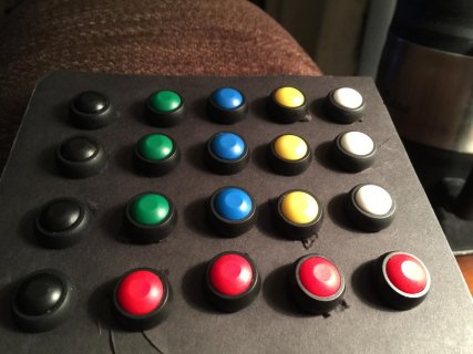
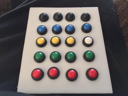
Received the rest of my parts today. Teensy 32 recognized by Windows 10 and my game. Template built for my button box layout. Build starts tomorrow.
My button box.jpg
 
The panel for my button box.
my button box panel.jpg

This will be the final design for my button box
Complete button box measurments.jpg
I was thinking about adding led strips to back light the box.
The panel is made out of 3.16" HDPE.
 
How are you planing to get at the underside contacts for the high numbered pins? Several ways to do it, just make sure you work out how BEFORE you start soldering stuff that will get in the way.

Also you are you trying to use A10-A13? They are not digital IO capable so can't be accessed via digital Read. If I'm reading your drawing right then you are are sticking to the GPIO pin range (gray numbered pins on the card) and it's all good.
 
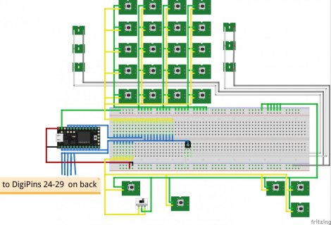
Pin Out

Pin A13 is not used.
I am running jumpers from the Teensy to terminal strips. Then running jumpers to the buttons. This way the buttons can be easily replaced.
I am also thinking about using A10 to source a NPN to control a LED strip to backlight the Opaque button panel.
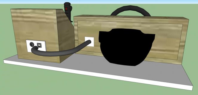
On the back of the button box is another HDPE panel.
This is where a USB B socket, a DC barrel, and cable to the dash panel will exit.
I have a USB B panel adaptor to a USB Micro connected to the Teensy32.
 

Attachments

  • My FS15 Controls back.jpg
    My FS15 Controls back.jpg
    49.5 KB · Views: 347
  • My FS15 Controls Front.jpg
    My FS15 Controls Front.jpg
    73.9 KB · Views: 1,084
Last edited:
A10 won't work as an output for the LEDs, since it's a special purpose analog in only. I don't think you are using digital 13 at the moment, the one with the fitted LED? That would be the easy one to drive the backlight from, though ideally you'd choose one with a pink 'PWM' label since they are the ones that would allow you to PWM the brightness using 'analogWrite'.

Depending on how you bright you want the backlight, it may be possible to run this from USB and be done with it. You should have about 300mA free out of the 500mA USB can reliably supply. Which will drive a small number of LEDs, probably not enough for daylight use, but probably ok if the aim here is parked on a desk indoors.
 
Updated photos in post 11 and 13 above.

I will check out the requirements for the LEDs then may remove the DC port. Power it all from the USB.
 
Circuit Sim

http://www.falstad.com/circuit/circuitjs.html

Does any use this java script?

My code for above site. Save as a txt file. Then import is in to Circuit Sim.

Code:
$ 1 0.000005 10.20027730826997 50 5 50
r 240 240 336 240 0 10000
s 336 240 432 240 0 1 true
s 336 272 432 272 0 1 true
r 240 272 336 272 0 10000
s 336 304 432 304 0 1 true
r 240 304 336 304 0 10000
s 336 336 432 336 0 1 true
r 240 336 336 336 0 10000
r 560 400 656 400 0 10000
s 656 400 752 400 0 1 true
r 560 368 656 368 0 10000
s 656 368 752 368 0 1 true
r 240 400 336 400 0 10000
s 336 400 432 400 0 1 true
s 336 368 432 368 0 1 true
r 240 368 336 368 0 10000
r 240 208 336 208 0 10000
s 336 208 432 208 0 1 true
r 240 176 336 176 0 10000
s 336 176 432 176 0 1 true
r 240 144 336 144 0 10000
s 336 144 432 144 0 1 true
s 336 112 432 112 0 1 true
r 240 112 336 112 0 10000
r 560 208 656 208 0 10000
s 656 208 752 208 0 1 true
r 560 176 656 176 0 10000
s 656 176 752 176 0 1 true
r 560 144 656 144 0 10000
s 656 144 752 144 0 1 true
s 656 112 752 112 0 1 true
r 560 112 656 112 0 10000
r 560 336 656 336 0 10000
s 656 336 752 336 0 1 true
r 560 304 656 304 0 10000
s 656 304 752 304 0 1 true
r 560 272 656 272 0 10000
s 656 272 752 272 0 1 true
s 656 240 752 240 0 1 true
r 560 240 656 240 0 10000
s 336 448 432 448 0 1 true
r 240 448 336 448 0 10000
s 336 480 432 480 0 1 true
r 240 480 336 480 0 10000
s 656 448 752 448 0 1 true
r 560 448 656 448 0 10000
s 656 480 752 480 0 1 true
r 560 480 656 480 0 10000
s 656 512 752 512 0 1 true
r 560 512 656 512 0 10000
w 240 112 240 144 0
w 240 144 240 176 0
w 240 176 240 208 0
w 240 208 240 240 0
w 240 240 240 272 0
w 240 272 240 304 0
w 240 304 240 336 0
w 240 368 240 336 0
w 240 400 240 368 0
w 240 480 240 448 0
w 560 512 560 480 0
w 560 480 560 448 0
w 752 512 752 480 0
w 752 480 752 448 0
w 752 400 752 368 0
w 752 368 752 336 0
w 752 336 752 304 0
w 752 304 752 272 0
w 752 272 752 240 0
w 752 240 752 208 0
w 752 208 752 176 0
w 752 176 752 144 0
w 752 144 752 112 0
w 752 112 752 64 0
w 752 64 432 64 0
w 432 64 432 112 0
w 432 112 432 144 0
w 432 144 432 176 0
w 432 176 432 208 0
w 432 208 432 240 0
w 432 240 432 272 0
w 432 272 432 304 0
w 432 304 432 336 0
w 432 336 432 368 0
w 432 368 432 400 0
w 432 448 432 480 0
w 432 480 432 528 0
w 240 448 240 432 0
w 240 112 240 48 0
w 560 48 560 112 0
w 560 112 560 144 0
w 560 144 560 176 0
w 560 176 560 192 0
w 560 192 560 208 0
w 560 208 560 240 0
w 560 240 560 272 0
w 560 272 560 304 0
w 560 304 560 336 0
w 560 336 560 368 0
w 560 368 560 400 0
R 160 48 112 48 0 0 40 3.3 0 0 0.5
w 560 48 240 48 0
w 240 48 160 48 0
S 432 528 336 528 1 2 false 0
r 240 512 336 512 0 10000
w 752 448 752 400 0
w 560 448 560 400 0
w 432 448 432 400 0
w 240 432 240 400 0
w 240 512 240 480 0
w 240 512 240 544 0
r 240 544 336 544 0 10000
g 432 528 432 560 0
w 336 112 336 96 0
w 336 96 192 96 0
w 336 144 336 128 0
w 336 128 192 128 0
w 336 176 336 160 0
w 336 160 192 160 0
w 336 208 336 192 0
w 336 192 192 192 0
w 336 240 336 224 0
w 336 224 192 224 0
w 336 272 336 256 0
w 336 256 192 256 0
w 336 304 336 288 0
w 336 288 192 288 0
w 336 336 336 320 0
w 336 320 192 320 0
w 336 368 336 352 0
w 336 352 192 352 0
w 336 400 336 384 0
w 336 384 192 384 0
w 336 448 336 432 0
w 336 432 192 432 0
w 336 480 336 464 0
w 336 464 192 464 0
w 336 512 336 496 0
w 336 496 192 496 0
w 336 544 336 528 0
w 336 528 192 528 0
w 656 512 656 496 0
w 656 496 512 496 0
w 656 480 656 464 0
w 656 464 512 464 0
w 656 448 656 432 0
w 656 432 512 432 0
w 656 400 656 384 0
w 656 384 512 384 0
w 656 368 656 352 0
w 656 352 512 352 0
w 656 336 656 320 0
w 656 320 512 320 0
w 656 304 656 288 0
w 656 288 512 288 0
w 656 272 656 256 0
w 656 256 512 256 0
w 656 240 656 224 0
w 656 224 512 224 0
w 656 208 656 192 0
w 656 192 512 192 0
w 656 176 656 160 0
w 656 160 512 160 0
w 656 144 656 128 0
w 656 128 512 128 0
w 656 112 656 96 0
w 656 96 512 96 0
M 512 96 480 96 0 2.5
M 512 128 480 128 0 2.5
M 512 160 480 160 0 2.5
M 512 192 480 192 0 2.5
M 512 224 480 224 0 2.5
M 512 256 480 256 0 2.5
M 512 288 480 288 0 2.5
M 512 320 480 320 0 2.5
M 512 352 480 352 0 2.5
M 512 384 480 384 0 2.5
M 512 432 480 432 0 2.5
M 512 464 480 464 0 2.5
M 512 496 480 496 0 2.5
M 192 528 160 528 0 2.5
M 192 496 160 496 0 2.5
M 192 464 160 464 0 2.5
M 192 432 160 432 0 2.5
M 192 384 160 384 0 2.5
M 192 352 160 352 0 2.5
M 192 320 160 320 0 2.5
M 192 288 160 288 0 2.5
M 192 256 160 256 0 2.5
M 192 224 160 224 0 2.5
M 192 192 160 192 0 2.5
M 192 160 160 160 0 2.5
M 192 128 160 128 0 2.5
M 192 96 160 96 0 2.5
 
On my project. Should I use the AREF and AGND for the switches for D0-D12 and D14-D27. There is a total of 27 switches in this project. Plus 1 led to indicate USB power connection. I see that the AREF is limited to 250mA. Each switch with 10k resistor will only pull 330uA. So I believe all should be good.

I had on set back on my project. I soldered all 27 resistors in place on my board. Thus covering all the needed solder pads on the single sided board. Now I have to wait a couple days for restock to arrive. I am short 7 resistors on the rebuild. There is no place local to get supplies.
 
You should be using inputMode(x,INPUt_PULLUP); for the switches so they don't need a high side connection (and therefore resistor), and then should be going to your digital (main ground). Everything you connect to analog ground will be adding noise to it, so keep the switches off it. If you are having noise severe enough to be mucking up a digital IO on a project this size then something is wrong.

see https://www.arduino.cc/en/Reference/PinMode and
 
Button issues???? Help needed.

My project is complete. Working 99%. I have issues with buttons connected to D11 and D23. Everything from the switch up to the Teensy pins checks out ok. Double checked the program and reloaded to the Teensy. The issue is still unresolved. Please help.

Code:
#include <Bounce.h>
Bounce button0 = Bounce(0, 10);
Bounce button1 = Bounce(1, 10); // 10 = 10 ms debounce time
Bounce button2 = Bounce(2, 10);  // which is appropriate for
Bounce button3 = Bounce(3, 10);  // most mechanical pushbuttons
Bounce button4 = Bounce(4, 10);
Bounce button5 = Bounce(5, 10);
Bounce button6 = Bounce(6, 10);
Bounce button7 = Bounce(7, 10);
Bounce button8 = Bounce(8, 10);
Bounce button9 = Bounce(9, 10);
Bounce button10 = Bounce(10, 10);
Bounce button11 = Bounce(11, 10);
Bounce button12 = Bounce(12, 10);
Bounce button14 = Bounce(14, 10);
Bounce button15 = Bounce(15, 10);
Bounce button16 = Bounce(16, 10);
Bounce button17 = Bounce(17, 10);
Bounce button18 = Bounce(18, 10);
Bounce button19 = Bounce(19, 10);
Bounce button20 = Bounce(20, 10);
Bounce button21 = Bounce(21, 10);
Bounce button22 = Bounce(22, 10);
Bounce button23 = Bounce(23, 10);
Bounce button24 = Bounce(24, 10);
Bounce button25 = Bounce(25, 10);
Bounce button26 = Bounce(26, 10);
Bounce button27 = Bounce(27, 10);


void setup() {
  pinMode(0, INPUT_PULLUP);
  pinMode(1, INPUT_PULLUP);
  pinMode(2, INPUT_PULLUP);
  pinMode(3, INPUT_PULLUP);
  pinMode(4, INPUT_PULLUP);
  pinMode(5, INPUT_PULLUP);
  pinMode(6, INPUT_PULLUP);
  pinMode(7, INPUT_PULLUP);
  pinMode(8, INPUT_PULLUP);
  pinMode(9, INPUT_PULLUP);
  pinMode(10, INPUT_PULLUP);
  pinMode(11, INPUT_PULLUP);
  pinMode(12, INPUT_PULLUP);
  pinMode(14, INPUT_PULLUP);
  pinMode(15, INPUT_PULLUP);
  pinMode(16, INPUT_PULLUP);
  pinMode(17, INPUT_PULLUP);
  pinMode(18, INPUT_PULLUP);
  pinMode(19, INPUT_PULLUP);
  pinMode(20, INPUT_PULLUP);
  pinMode(21, INPUT_PULLUP);
  pinMode(22, INPUT_PULLUP);
  pinMode(23, INPUT_PULLUP);
  pinMode(24, INPUT_PULLUP);
  pinMode(25, INPUT_PULLUP);
  pinMode(26, INPUT_PULLUP);
  pinMode(27, INPUT_PULLUP);
}

void loop() {
  button0.update();
  button1.update();
  button2.update();
  button3.update();
  button4.update();
  button5.update();
  button6.update();
  button7.update();
  button8.update();
  button9.update();
  button10.update();
  button11.update();
  button12.update();
  button14.update();
  button15.update();
  button16.update();
  button17.update();
  button18.update();
  button19.update();
  button20.update();
  button21.update();
  button22.update();
  button23.update();
  button24.update();
  button25.update();
  button26.update();
  button27.update();
  
  if (button0.fallingEdge()) {
    Joystick.button(13, 1);
  }
  if (button1.fallingEdge()) {
    Joystick.button(1, 1);
  }
  if (button2.fallingEdge()) {
    Joystick.button(2, 1);
  }
  if (button3.fallingEdge()) {
    Joystick.button(3, 1);
  }
  if (button4.fallingEdge()) {
    Joystick.button(4, 1);
  }
  if (button5.fallingEdge()) {
    Joystick.button(5, 1);
  }
  if (button6.fallingEdge()) {
    Joystick.button(6, 1);
  }
  if (button7.fallingEdge()) {
    Joystick.button(7, 1);
  }
  if (button8.fallingEdge()) {
    Joystick.button(8, 1);
  }
  if (button9.fallingEdge()) {
    Joystick.button(9, 1);
  }
  if (button10.fallingEdge()) {
    Joystick.button(10, 1);
  }
  if (button11.fallingEdge()) {
    Joystick.button(11, 1);
  }
  if (button12.fallingEdge()) {
    Joystick.button(12, 1);
  }
  if (button14.fallingEdge()) {
    Joystick.button(14, 1);
  }
  if (button15.fallingEdge()) {
    Joystick.button(15, 1);
  }
  if (button16.fallingEdge()) {
    Joystick.button(16, 1);
  }
  if (button17.fallingEdge()) {
    Joystick.button(17, 1);
  }
  if (button18.fallingEdge()) {
    Joystick.button(18, 1);
  }
  if (button19.fallingEdge()) {
    Joystick.button(19, 1);
  }
  if (button20.fallingEdge()) {
    Joystick.button(20, 1);
  }
  if (button21.fallingEdge()) {
    Joystick.button(21, 1);
  }
  if (button22.fallingEdge()) {
    Joystick.button(22, 1);
  }
  if (button23.fallingEdge()) {
    Joystick.button(23, 1);
  }
  if (button24.fallingEdge()) {
    Joystick.button(24, 1);
  }
  if (button25.fallingEdge()) {
    Joystick.button(25, 1);
  }
  if (button26.fallingEdge()) {
    Joystick.button(26, 1);
  }
  if (button27.fallingEdge()) {
    Joystick.button(27, 1);
  }
  if (button0.risingEdge()) {
    Joystick.button(13, 0);
  }
  if (button1.risingEdge()) {
    Joystick.button(1, 0);
  }
  if (button2.risingEdge()) {
    Joystick.button(2, 0);
  }
  if (button3.risingEdge()) {
    Joystick.button(3, 0);
  }
  if (button4.risingEdge()) {
    Joystick.button(4, 0);
  }
  if (button5.risingEdge()) {
    Joystick.button(5, 0);
  }
  if (button6.risingEdge()) {
    Joystick.button(6, 0);
  }
  if (button7.risingEdge()) {
    Joystick.button(7, 0);
  }
  if (button8.risingEdge()) {
    Joystick.button(8, 0);
  }
  if (button9.risingEdge()) {
    Joystick.button(9, 0);
  }
  if (button10.risingEdge()) {
    Joystick.button(10, 0);
  }
  if (button11.risingEdge()) {
    Joystick.button(11, 0);
  }
  if (button12.risingEdge()) {
    Joystick.button(12, 0);
  }
  if (button14.risingEdge()) {
    Joystick.button(14, 0);
  }
  if (button15.risingEdge()) {
    Joystick.button(15, 0);
  }
  if (button16.risingEdge()) {
    Joystick.button(16, 0);
  }
  if (button17.risingEdge()) {
    Joystick.button(17, 0);
  }
  if (button18.risingEdge()) {
    Joystick.button(18, 0);
  }
  if (button19.risingEdge()) {
    Joystick.button(19, 0);
  }
  if (button20.risingEdge()) {
    Joystick.button(20, 0);
  }
  if (button21.risingEdge()) {
    Joystick.button(21, 0);
  }
  if (button22.risingEdge()) {
    Joystick.button(22, 0);
  }
  if (button23.risingEdge()) {
    Joystick.button(23, 0);
  }
  if (button24.risingEdge()) {
    Joystick.button(24, 0);
  }
  if (button25.risingEdge()) {
    Joystick.button(25, 0);
  }
  if (button26.risingEdge()) {
    Joystick.button(26, 0);
  }
  if (button27.risingEdge()) {
    Joystick.button(27, 0);
  }
}
 
My thought would be to verify your buttons by adding a 'Serial.println("button 11 pressed");' to see if the hardware is working, you could also try swapping the joystick(11,x) lines for button 10/12 and 22/23 around to see if it's something oddball in the joystick code or the computer side driver.

Also, how are you testing the buttons, in game or through the windows setting panel?
 
Nothing shows on the serial monitor for D11 or D23. But works 100% if wired to pins D28 & D29. Si I guess that the D11 & D23 pins are malfunctioning.
 
by way of sanity check suggest making a basic test sketch

void setup{
pinMode(11,INPUT_PULLUP);
pinMode(13,OUTPUT);
}
void loop
{
if(digitalRead(11)==HIGH) digitalWrite(13,LOW); else digitalWrite(13,HIGH);
delay(50);
}

and do a re-check that the pins are in fact connected properly and change voltage when the button is pressed (if it does all work, the LED should indicate button state). Otherwise yes, it would like like the input is damaged in some way, though it's interesting that it appears to be damaged in a way that it's pullup still works.
 
Status
Not open for further replies.
Back
Top