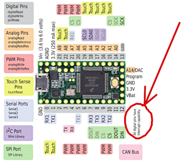
Teensy 3.1/3.2: PWM Input (digital interrupts)

Status
Not open for further replies.

synfinatic

Active member
I'm looking at building a project using a Teensy 3.1/3.2 with 4-12 Melexis MLX90614 IR temp sensors. The sensors support SMBus (I2C) as well as PWM output, but I'd like to use the PWM mode since it means I won't have to assign a unique slave ID for each sensor and means I can read the temperatures constantly.

The challenge of course is with that many PWM inputs going all at once, I'd definitely need to be using interrupts to measure the signal. I thought there was information about the number of pins with interrupts on the Teensy 3.1 on the PJRC website, but I can't find it anymore??? Would love to figure out which digital pins support interrupts.

Thanks!
 
I thought there was information about the number of pins with interrupts on the Teensy 3.1 on the PJRC website, but I can't find it anymore???

It's on the reference card that came with your Teensy, which you can get download here too.

card7a_rev1.png
 
Are the pins using shared interrupts or is there an interrupt per pin? I assume I'd want to distribute things across as many interrupts as possible. Also, I totally forgot about the Teensy-LC, seems like that should work too?
 
There's an interrupt per port.
The interrupt routine then determines which pin triggered the interrupt and redirects to that pin's assigned interrupt function.

If you want more than 4 interrupts this overhead is unavoidable. I can't comment on the LC though, sorry!
 
Have you completed you PWM programming?
I am using 3.2 with two MLX90614 and not finding any code examples would very much appreciate to see your approach.
I will be setting the period so that the data stream is repeated at ~10 Hz
Will be using dual zones and sending sensor1 and sensor2 data in each stream.
 
I am using 3.2 with two MLX90614

This chip has I2C. Why use the pulses when you can get the digital data directly with the Wire library?

To connect two sensors, use the regular SDA & SCL pins (18 & 19) for the first sensor, and the alternate pins (17 & 16) for the other sensor. Don't forget to add 4 pullup resistors to 3.3V. To switch between the sensors, use Wire.setSCL(pin) and Wire.setSDA(pin).
 
You are right Paul, it is far easier.
I was looking for a programming challenge using interrupts and clocks/timers, and the appearance that it has not been done yet on Teensy.
The simplicity to add sensors to our products without the need to assign different I2C addresses, risking mix-ups when assembling our products.
According to the datasheet the sensors can be added to our PCBs to allow alternating between I2C and PWM modes with the ability to use the thermal relay mode while in PWM mode, indirectly triggering a relay when temperature thresholds are met.
The datasheet indicates that the precision is greater in PWM mode.
Many configuration options are modifiable by the user, including changing the I2C address.
 
If you want a challenge to read PWM the best possible way, you certainly can do with so the FTM timers input capture. Look at the FreqMeasure and PulsePosition libraries to get started. These read the time between successive rising edges, so you'll need to do a little work to read the time between a rising and falling edge.

This could also be done using attachInterrupt and micros or reading ARM_DWT_CYCCNT. Obviously that won't be as good as using input capture on a fast incrementing timer, but if the interrupt is configured to high priority it'll probably be good enough since this chip outputs ~976 Hz PWM with 1 us step size.
 
If you want a challenge to read PWM the best possible way, you certainly can do with so the FTM timers input capture. Look at the FreqMeasure and PulsePosition libraries to get started. These read the time between successive rising edges, so you'll need to do a little work to read the time between a rising and falling edge.

Yep, or take a look here for a simple code that uses the input capture for a "any-protocol" non-blocking ir-receiver .
 
Also worth considering is the PWM signal only gives you (at best) 10 of the 17 bits this sensor has. I2C seems like a much better approach.
 
paul and frank, really appreciate your guidance.
after we do the initial temp reading tests to select single or dual zone sensors and their position, I will begin the attempt to program PWM.
We will likely implement with I2C, but I will design the circuitry for both I2C and PWM. I will post my code here for review and assistance.
I must say also that selecting the Teensy was the best decision we have made so far because of your support.
Thanks again...
www.beatenpath.ca
 
Status
Not open for further replies.
Back
Top