How does TouchRead do its measurment?

Status
Not open for further replies.

Aduen

New member
Hi,

I was expecting the touchRead() to perform according to a RC time circuit but it seems to do exactly the opposite... :) I understood that the actual number that is displayed should come close to the actual capacitance in Farad (or a denomination of it).
Now, when I feed it an RC time circuit, variable resistor (1-50Kohm) and ceramic capacitor (100nF) and slowly turn down to Ohms I see the number returned from touchRead() increase. Where I expected it to decrease, less resistance equals faster charging cycles... When I used the same circuit and did a "normal" RC time measurment using a regular GPIO I got the expected result.

How does touchRead() work?

Kind regards,
Aduen
 
Connect only the capacitor, not a resistor.

Internally, it uses transistor-controller constant current sources, not resistors. During the measurement, small test currents flow in and out of the Teensy pin to your capacitor.

In performs the measurement simultaneously (using matched circuits) on an internal reference capacitor and on your external capacitor. The currents charge and discharge both capacitors between a couple voltage levels, and the time required to do so is measured. The times for both capacitors are compared, which compensates for temperature-dependent effects in the transistors and voltages, giving a very stable result.
 
Section 50.3.1 explains it in the datasheet
The electrode oscillator charges and discharges the pin capacitance with a programmable
current source to accommodate several different sizes of electrode capacitances. The
electrode oscillator frequency, before being compared to that of the reference oscillator,
goes through a prescaler and module counter to decrease its frequency and consecutively
increase the measurement resolution and noise robustness.

I'd be interested to know exactly how this works

EDIT -
It's explained very clearly from 1355 onwards.
Effectively the external capacitor under test is used to create an oscillator. This is then compared against a known frequency to determine the frequency and thus the capacitance

A pretty clever way of doing it. I was more familiar with the method employing an external RC circuit like you stated Aduen
 
Last edited:
Hey Paul, thanks for the fast response!

The reason I had that resistor in there was because I was simulating a sensor. I was thinking of using touchRead() to read out the sensor. The sensor is a pressure sensor (piezo-resistive) with the addition of a capacitive layer to extend the dynamic range beyond just pressure. Anyway....

I understand now, the current control is the reason. And I get the "hardware referenced capacitance measurement" I read about :)

Maybe I alternate rc time logic and touchRead() on the same pin... Could give some very fine and stable results with a huge dynamic range...

Thank you so much!
 
I am able to read the result of touchread() function and reproduce the experiment using a copper strip
I have gone through the forums and ,and have understood that adding a resistor will increase sensitivity.

What units is the reading of capacitance ? Without touch the values for NO touch is the same. However the value for TOUCH is very very large. Below is an example

with a low resistance 500K

850
850
890 <----touch
900
850
850 < no touch

with 1M ohm resistor
850
850
1400 <----touch
1500 <--touch
850
850 < no touch


In this case what does the high values of 890 /1500 actually mean in terms of Farads ? Or is it just a relative reading, and the project has to calibrate (convert) it in terms of Farads.
 
Adding a resistor will not increase sensitivity. The teensy uses an LC tank resonating circuit coupled with an onboard capacitor as a hardware reference. Your capacitance changes the resonating frequency. Adding a resistor will only mess up the equation. I think the output is in femto farad. All the wire and plates you add to the sensor circuit will have some capacitance to start with, without touching it.
 
Fascinating, it's awesome to learn how these things work.

If I understand correctly, it's measuring capacitance at a certain AC frequency, so isn't that essentially impedance? And if not, I'm curious to know how different it is from impedance.
 
What it actually measures is a period of time, because that is what micros excel at (using, you guessed it, a timer). That measured time is the period of the oscillator (1/f). From there on the causal chain is as Aduen said in post 6. More capacitance means lower frequency means longer periods.
 
Yes, that makes perfect sense and clever.

I guess my real question is, can we expect that this filling time has a linear relation to impedance?
 
Off the top of my head: T=sqrt(LC), so no, not linear.

Edit: well the measurement itself in not linear, but maybe the generated readings are linearized?
 
Ok, I guess my real question this time is: Can the touchread measurement be mapped (square transform, etc) for a 1:1 with impedance?
 
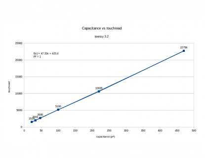
The touchRead() output is supposed to be linear with capacitance.

As a quick sanity check, I just tried running this on a Teensy 3.2:

Code:
void setup() {
}

void loop() {
  Serial.println(touchRead(0));
  delay(10);
}

Then I tried poking some through-hole capacitors into pin 0 and GND, with the board resting as a slight angle so its weight caused contact with the capacitor's leads.

Here's the numbers I saw:

nothing (stray PCB capacitance) = 467
22pF = 1529
33pF = 2001
47pF = 2680
100pF = 5160
220pF = 10635
470pF = 22756

I did this quickly, trying just one of each capacitor (which are probably 10% tolerance). Some of the readings varied a little, so I just wrote down what visually seemed like the most commonly printed number. Just quick & dirty testing...

I suppose if someone wanted to know how linear the response really is, they could plot these numbers on a graph or something? Or maybe even do more meticulous measurement with tighter tolerance capacitors?
 
Well, I guess that answers that. Here's the graph. Very nice!

touchreadVScapacitance.png

View attachment touchreadVScapacitance.pdf
 
Wow, that worked out quite a bit better than I'd imagined it would, especially for old through-hole ceramic disc capacitors than have been sitting in the bottom of my parts draws for many years.
 
FWIW, I would play close attention to proper grounding and/or use relative measurements / offsets out of the ADC as triggers rather than absolute numbers. When I tried using a DIY external capacitive sensor to measure water level in a tank, the readings could drift considerably. That may have had to do with what was in the tank (ultrasonic emitter) but the results were sufficiently erratic for water level control in this application that I switched to a optical sensor instead.
 
Status
Not open for further replies.
Back
Top