Gameport Yoke & Pedals USB Conversion

CRNorris

Member
Hi,

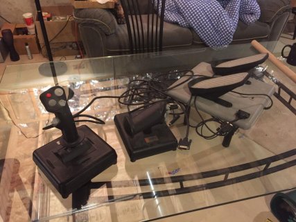
I’ve got an old CH Products Virtual Pilot Pro yoke and Pro Pedals here, and they use the old gameport interface.

I was originally going to put a Teensy inside the chassis of each, wired directly to the potentiometers and buttons. For the potentiometers (of which there is one per axis), I was going to connect one end of the pot to 3.3V, the other end to AGND and the wiper to an Analog Pin. (Essentially I would copy this approach)

But then I found out from this page that I could interface the yoke and pedals with the Teensy without modifying them, because apparently gameport joysticks “use their potentiometers as voltage dividers – this means you need to add a 100kΩ resistor between the Teensy pin and ground” for each axis.

So whereas I was thinking I would need to put one Teensy in the yoke chassis and a second Teensy in the pedals chassis, modifying the units as necessary, now I think I’d prefer to get some gameport style sockets and connect them to just one Teensy inside an enclosure, with the yoke and pedals unmodified, simply plugging in as they did with a PC in the 1990s.

So my question is, which approach is better in your opinion?

I have no problem with modifying the yoke and pedals if it’s the better approach but if the precision etc. will be the same (or not noticeably different) if I build an interface box, then I’d rather do that.

(Plus I already have a spare enclosure and stripboard that I think would be suitable)

I already have two Teensy 3.2s ready for this project, but if I only have to use one that would be useful. These things are awesome.

I'd really appreciate your guidance before I sacrifice quality just to save a bit of effort and money, thanks!
 
Hello CRNorris,

I read your post with interest because I have a set of CH Pro Pedals and a Flight Stick Pro with the game port interfaces that I'm considering converting to USB with Teensy, mostly as a learning exercise.

Have you made any decisions or progress on your conversion?

Based on what I've learned thus far, and I'm still very much a beginner at this, I'd suggest that the answer to your question about whether it would be preferable to embed a Teensy in both your pedals and yoke or build a box with a single Teensy and game port input depends upon which functions of the yoke and pedals you want to utilize as well as several tradeoffs in the design and implementation.

For example, I'd like to use the three linear axes of the pedals to control yaw and left/right toe brake. Is this similar to how you want to use the pedals?

It's possible to do this with the existing game port connectors, but I'm not yet sure if it's the best approach.

With the pedals in "PLANE" mode, the pot wiper for the yaw axis is accessible as pin 11 of the DA-15 labeled "GAMEPORT". The pot wipers for the axes I'd use for the toe brakes on are pins 3 and 6 of the "AUXPORT" DA-15. One terminal of each pot is connected to pin 1; the other terminal of each pot is not connected. With these pins it is possible to create voltage dividers for each axis and connect each to the Teensy in a design similar to the diagram you found.

So here is one tradeoff: to utilize three axes from the pedals with a custom adapter box you'll need to connect both the "GAMEPORT" and "AUXPORT" connectors.

Another tradeoff is how to compensate if the 100K pots produce jitter in the USB reports. As I understand it, and someone please correct me if I'm mistaken, analog readings of a 100K pot are likely to exhibit more variance than a 10K pot.

As an experiment, I removed one of the 100K pots from the pedals and connected it directly to the Teensy 3.2 as a voltage divider: +3.3V from the Teensy to one terminal, wiper to A0, other terminal to AGND. Starting with the Joystick example sketch and the Teensy in USB Keyboard/Mouse/Joystick mode, I monitored the output of the Teensy in a USB joystick calibration window. With no movement of the pot, the graphical depiction for that axis jumped around enough that it seems likely that the sim would receive spurious control input.

The How to reduce noise from analog pins? thread discusses several approaches for quieting this down. Wiring in a small capacitor is one option. I didn't have one on hand so I tried a software technique. This combination decreased the magnitude of the jitter quite a bit:

Code:
void setup() {
  analogReadRes(8);
  analogReadAveraging(32);
}

void loop() {
  // read analog inputs and set X position
  delayMicroseconds(10);
  Joystick.X(analogRead(0));

  // a brief delay, so this runs 20 times per second
  delay(50);
}

but there was still more jitter than I observed with a commercial USB gamepad.

Whether the 100K pot, either before or after reducing the jitter with software or a capacitor, will make a difference in the actual sim control, I'm not yet sure.

Another set of questions and tradeoffs must be considered with the yoke. How many linear axes, buttons, hat switches, etc. do you want to utilize? Does your yoke have a single game port connector or multiple?
 
Hi mfremont,

Thanks for your reply and yes I've made a decision.

In the end I just tried connecting a pot up with an extra 100k resistor and used it as a joystick axis. The results were that it worked, but of course I wasn't using the full range of the Teensy's analog input because of the extra 100k resistor.

Performing calibration of the joystick in the OS made it usable, but I didn't like the idea of sacrificing precision; I've got to make something either way, so I chose the approach that would give me the highest precision (even if it's not necessarily noticable in-game!).

I was testing with a 25k pot, and that made my test unfair (which I realised later) because I was still using the big 100k resistor, but it did serve to illustrate the issue with the limited range.

Since I hadn't tried that test with a 100k pot , I wasn't aware of the jitter problem you describe - so thanks for the information, this is very useful. I have some random capacitors so I'll try that technique out and report back.

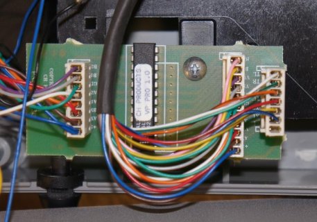
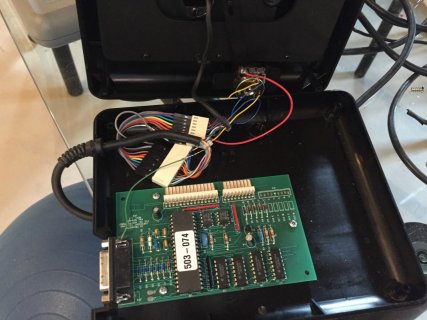
The yoke would have been fiddlier than I expected to interface with through the gameport. There was a chip in it that I assume was doing something like encoding the button states using the few digital inputs provided by the gameport; then I guess a driver had to be installed on the PC to decode the button states and expose them properly to games. So I would have had to reverse engineer that, which wouldn't have been difficult but is another reason not to bother making a converter box.
 
Hi again,

Just reporting back as promised to say that firstly yes, you're right about the jitter! It's far worse than I would have expected.

But the good news is the capacitor trick works.

I found a 22nF ceramic capacitor and just put it in there between the ADC pin and AGND as Paul suggested in the thread you linked to. He said 1nF but if I understand right, the capacitance can't really be "too high" in this instance, the excess will just be unused. (I'd appreciate if someone could confirm that!)

Without even changing my delay, and with everything like resolution at its defaults, I immediately saw a dramatic improvement in the jitter, in fact it's all but gone. If I use the Windows USB Game Controllers calibration tool, I can see I have 1024 steps, and it jitters between the two neighbouring values (e.g. between 176 and 177 and between 946 and 947) which isn't enough to change the overall percentage. It's pretty nice to be able to rotate the pot and observe the 10 bits of precision.

I should think it will be possible to improve the performance further by increasing the delay and/or implementing a software solution as you suggested.

Is there any kind of downside to using a capacitor in this way do you think? I'm assuming it's better than your software solution but how can we determine if that's actually true?
 
Thanks for sharing your result. I was planning on ordering a few capacitors to experiment with. Based on what you found, I may try some both bigger and smaller to see what the effect is.

I'm curious: with the 22nF capacitor is the magnitude of the jitter is larger with the pot centered compared to a position near either the min/max value?

My background is not EE, but if my nascent understanding of ADC measurement theory (primarily from the Freescale Cookbook for SAR ADC measurements) is going in the right direction, the magnitude of the jitter is likely to be largest at center since the impedance of the pot is at its maximum.

Even with no capacitor and no averaging, using just the example AnalogInput sketch, I see more variance in the result from analogRead() with the 100K pot at center compared to positions near the min/max (~20º on either side of center for this particular pot). With 10 bits, I see values that range from ~499-533 around the center pot position, whereas near the min/max the values are more stable, fluctuating in a range +/-2.

For comparison, a voltage divider using two fixed 10K resistors results in a 10-bit value of 510-511.

With regard to using a capacitor vs. software to obtain a stable reading, my sense at this point is that it is a combination of the two. The capacitor helps to stabilize the analog circuit, which, in turn, allows for digital readings with less variance. The tradeoff here is that you can't detect a change as fast, and with the 100K pot, you also have to give up some bits of precision. The magnitude of the analog source resistance and capacitance also affects the time required for the ADC to acquire a stable reading. This is where software configuration of the ADC precision and acquisition time comes in.

Although we could probably achieve greater precision and shorter acquisition times with 10K or 5K pot, perhaps this is not necessary to achieve good fidelity for the flight sim?

If the sim frame rate is in the range of 60-120Hz, is that a factor for determining the sample rate we need to achieve with the Teensy?

Your results with the 22nF capacitor are promising. It seems possible that we can achieve acceptable control for the sim with the 100K pot and a little tuning of the circuit and software.

If my understanding or inferences on any of these points are mistaken, I hope someone will jump in to correct that. :)
 
Last edited:
Cool... I've got the same exact yoke and pedals that I'm looking to convert to USB as well, so I'm definitely interested in what you come up with.

I want to be able to use the pedals with my Teensy controlled HOTAS ( https://forum.pjrc.com/threads/3337...Teensy-MCU-mod-(USB-Flight-Joystick-Throttle) ), so ideally I'd be able to just put a DB-15 connector on that, and read the pedals without any modifications.

For the yoke, I think I read somewhere about the hat and buttons being "chorded", so you can't really press more than one button at a time using the standard gameport wiring... so I'll probably do a similar setup to my HOTAS by putting the Teensy inside (so I can connect the switches directly to input pins), and then repurpose the old cable/connector as an input from the pedals.

Pat
 
Re the size of the smoothing capacitor, you make it as large as you can without impacting your time for full deflection.

https://en.wikipedia.org/wiki/RC_circuit

So as you make the capacitor larger you get to a point where if you start at full deflection (say 0) and jump to the middle the time to charge through a 50k resistance becomes more than the time to physically move your control input and you start seeing lag and or/overshoot. Other things to reduce noise include adding ferrite chokes to the input wires to cut down RF, making sure your Cap is as close to the input as it can physically, ensureing your power to the pots is stable (keep blinky LEDs and motors off that supply, and possibly filter it) and tightening up the EMI shielding for the design.

When you have added temperature compensation and are sleeping the CPU during the ADC read to avoid clock noise you are possibly getting overkill for a controller.
 
For the yoke, I think I read somewhere about the hat and buttons being "chorded", so you can't really press more than one button at a time using the standard gameport wiring

The buttons were fed into an Atmel ATF20V8B-25PC, and a lot fewer wires came out of that towards the gameport than went in on the other side, so that seems highly plausible.
 
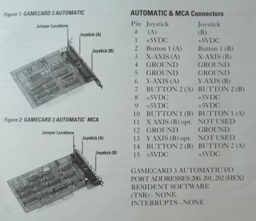
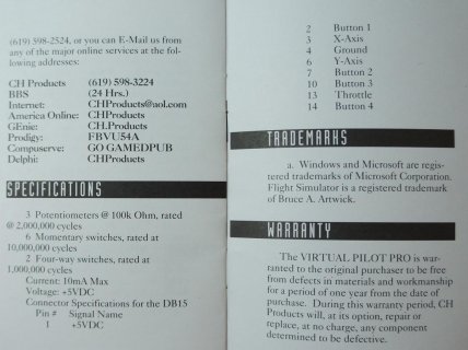
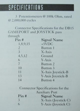
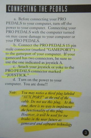
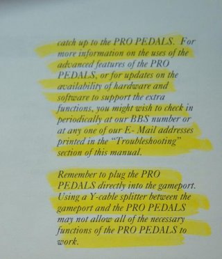
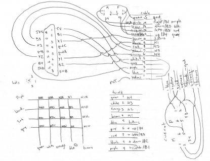
I haven't really started on the project yet, but I did come across my manuals from the CH gameport card, yoke, and pedals... I noticed they had the pinouts listed, so I figured I'd post them here. Obviously it's basically just the 15-pin joystick pinout, but figured I'd post it since there's a little bit of information specific to this hardware.

gamecard.jpg

yoke.jpg

pedals.jpg

Pat
 
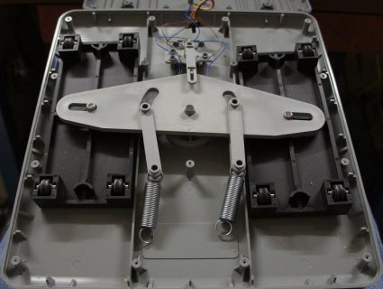
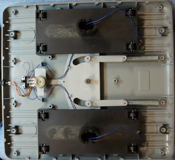
Okay, I opened up the pedals... bad idea. ;)

SPROING!!!
doh.jpg

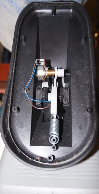
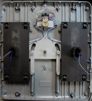
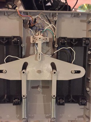
If you take the bottom off, everything falls apart (parts come undone, spring pops off, etc). To reassemble, you need to basically take the thing completely apart and reassemble from scratch. That involves undoing the wires, removing the pedals from the top, assembling all the parts on the base, clipping the wires back in place, putting the top on, and reattaching the pedals. And there's really nothing worth seeing inside... just wiring, pots, a switch, and mechanical stuff (below are some pics for the curious).

Reassembled on the base:
rebuilding.jpg

Inside a pedal:
pedal.jpg

Pat
 
The 22nF cap, averaging set to 32 and resolution at 10 bit is quite good. There's still some jitter occasionally though, as if the pot is half way between two values.

I'm tempted to just do something like check if the new value differs from the last one by more than 2. That would appear to fix the jitter I think, but what's the downside?

Related to that, is there any advantage in checking if the new value read is different from the last one read and only updating the joystick if it is? Less USB traffic..?

Other things to reduce noise include adding ferrite chokes to the input wires to cut down RF, making sure your Cap is as close to the input as it can physically, ensureing your power to the pots is stable (keep blinky LEDs and motors off that supply, and possibly filter it) and tightening up the EMI shielding for the design.

Thanks for the info. For ferrite chokes, is that just a ferrite ring with the wire to the analog input looped through it several times? If so, would each analog input lead have its own?

And for getting the cap close to the input, does that mean I should put the cap close to the Teensy, or close to the pot?

Also I assume I should be using the AGND for analog inputs and GND for digital inputs.

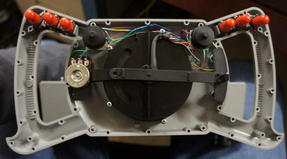
In the yoke, the actual wheel part of it just has switches and pots, with wires going back to the base which is where the teensy will live. I don't really want to re-do those wires since they've already been routed through the shaft for me. There are enough wires, but the ground wire is actually two wires that go into one pin in the connector. Has that been done so that the ground wire can carry the current required if all the buttons are pressed at once or what do you think?

Ideally I'd like to take one of those ground wires off the pin and use it for AGND, with the other being used as GND (for the buttons and hat switches) but I'd appreciate guidance on whether that's a good idea.

DogP, do you think it would be easier to disassemble the pedals by removing the caps from pedals first? I haven't opened mine up yet.

Thanks for all your help, this is shaping up nicely.
 
Thanks for posting the documents. It seems to confirm what I was able to discern in testing the GAMEPORT, AUXPORT, and JOYSTICK connectors on the pedals. The detail that is not clear from the docs is how the PLANE/CAR slide switch changes what is connected to pins 11 and 13 of the GAMEPORT connector.

From testing with the DMM, it looks like in PLANE mode

pinfunction
11yaw axis, i.e. the center pot
13pass-through from JOYSTICK pin 13

and in CAR mode:

pinfunction
11left pedal
13right pedal

As I noted in my earlier post, the individual left/right pedal axes are also output on pins 3 and 6, respectively, of the AUXPORT connector. This is the case regardless of the position of the PLANE/CAR switch.

Ah, the "SPROING!" I was a bit surprised by that, too, when I opened up my pedals a couple of weeks ago.

My tentative plan is to mount a Teensy inside the base and wire each pot as a voltage divider using all three terminals on each. Since that will require an additional wire from each pot, I'm guessing that I will be fully disassembling it anyway.

For the wiring to the terminal tabs on the pots, I'm going to try Molex connector 35711-0610. It fits the terminals on the pot and has a positive "click" once you push it on far enough.
 
The 22nF cap, averaging set to 32 and resolution at 10 bit is quite good. There's still some jitter occasionally though, as if the pot is half way between two values.

Good to hear. I'm waiting on the caps I ordered. I'll report back once I get a chance to do some experimentation using the caps.

I'm also curious whether 10 vs. 8 bit resolution makes any significant difference for sim control. I flew the X-Plane 10 demo today with an old CH USB yoke that is 8-bit on each axis and it seemed just fine. Some of the newer products offer 10 bit resolution.

I'm tempted to just do something like check if the new value differs from the last one by more than 2. That would appear to fix the jitter I think, but what's the downside?

I think you're effectively loosing 1 bit of precision for small movements of the controls, but for larger movements you get the full 10 bits of precision?

And for getting the cap close to the input, does that mean I should put the cap close to the Teensy, or close to the pot?

My understanding is that the cap should be close to the analog input pin of the Teensy.

Also I assume I should be using the AGND for analog inputs and GND for digital inputs.

That's what I understand from the threads on analog input.

There are enough wires, but the ground wire is actually two wires that go into one pin in the connector. Has that been done so that the ground wire can carry the current required if all the buttons are pressed at once or what do you think?

Ideally I'd like to take one of those ground wires off the pin and use it for AGND, with the other being used as GND (for the buttons and hat switches) but I'd appreciate guidance on whether that's a good idea.

By "the connector" are you referring to the game port DA-15 connector? Which pin?

Are all three terminals of each pot in the yoke connected? I ask because in the pedals only only two of the terminals on each pot are connected. You can see this in the photos that DogP posted. As far as I can tell from the pedals I have, each pot is only connected to the game port +5V pin and one of the axis pins. There are no connections to the game port ground pin for any of the pots. Maybe the yoke is different...

If you want to use the existing pots as linear voltage dividers, you need to connect the third terminal of each to AGND. Is this what you are describing?

Maybe a photo or a diagram of what you're trying to describe would help?
 
The 22nF cap, averaging set to 32 and resolution at 10 bit is quite good. There's still some jitter occasionally though, as if the pot is half way between two values.
I personally wouldn't worry about a tiny bit of jitter... 1 bit at 10-bit resolution is about 0.1%, which should have almost no effect in the game. One thing I did notice while working on another project is that the current analog read would be affected by the previous analog read (from another channel). So, I put "dummy" analog reads of a digital pin with a pullup between each read that I cared about... like:
x=analogRead(A1);
analogRead(A9); //dummy read
y=analogRead(A2);
analogRead(A9); //dummy read

There are enough wires, but the ground wire is actually two wires that go into one pin in the connector. Has that been done so that the ground wire can carry the current required if all the buttons are pressed at once or what do you think?
I haven't opened mine yet, but there's VERY little current, so I doubt they used two wires for current capacity. It's probably just a simple case that they needed the ground wire to go to two different places, so they joined them at the connector pin rather than somewhere else down the line.

Ideally I'd like to take one of those ground wires off the pin and use it for AGND, with the other being used as GND (for the buttons and hat switches) but I'd appreciate guidance on whether that's a good idea.
Maybe someone can correct me if they know otherwise... but I don't think it's particularly necessary to reference buttons to (digital) GND. I connected my buttons to AGND in another project, and checked whether the readings were any different when buttons were pressed, and I couldn't see any effect. The pins are pulled up with very weak pullups, so the amount of current sunk into AGND by a button press is tiny, and noise induced from the power rail should be minimal, again, since the pullup is so large.

DogP, do you think it would be easier to disassemble the pedals by removing the caps from pedals first? I haven't opened mine up yet.
Yes, if I take them apart again, I'll definitely take the pedals off first, and then all the screws off the bottom (but hold the entire assembly together), and then lift the top off the base. That should keep everything together.

Thanks for posting the documents. It seems to confirm what I was able to discern in testing the GAMEPORT, AUXPORT, and JOYSTICK connectors on the pedals. The detail that is not clear from the docs is how the PLANE/CAR slide switch changes what is connected to pins 11 and 13 of the GAMEPORT connector.

From testing with the DMM, it looks like in PLANE mode

pinfunction
11yaw axis, i.e. the center pot
13pass-through from JOYSTICK pin 13

and in CAR mode:

pinfunction
11left pedal
13right pedal

As I noted in my earlier post, the individual left/right pedal axes are also output on pins 3 and 6, respectively, of the AUXPORT connector. This is the case regardless of the position of the PLANE/CAR switch.
Yes, I think that's correct. The manual mentions that technology would eventually catch up to the pedals and use the AUXPORT connector for the toe brakes. So, the assumption would be that for racing games you'd want the "toe" inputs (gas/brake), and for flight sims, you'd want the rudder.

DSC03537.JPG

DSC03538.JPG

Ah, the "SPROING!" I was a bit surprised by that, too, when I opened up my pedals a couple of weeks ago.
Well thanks for the heads up. ;)

Are all three terminals of each pot in the yoke connected? I ask because in the pedals only only two of the terminals on each pot are connected. You can see this in the photos that DogP posted. As far as I can tell from the pedals I have, each pot is only connected to the game port +5V pin and one of the axis pins. There are no connections to the game port ground pin for any of the pots. Maybe the yoke is different...

If you want to use the existing pots as linear voltage dividers, you need to connect the third terminal of each to AGND. Is this what you are describing?
I believe the standard 15-pin analog joystick connection has always been a 100K pot to +5V (not a voltage divider across +5V and GND), so I'd guess the yoke is connected the same way. So yes, you can either add another wire and turn it into a voltage divider, or add your own resistor to GND at the input to create a voltage divider. In theory, I don't like the resistor method as much, since it's not symmetric, which may cause more jitter at one end than the other... and you're throwing away amplitude, which decreases your SNR. But, it's more convenient since you can use it as-is.

Pat
 
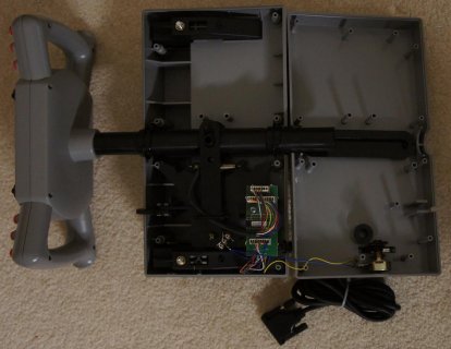
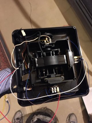
I popped my yoke apart last night... looks like it should be pretty easy to modify. The pots are wired like the other, 100K to +5V (no GND). Here are a few pics in case you're curious.

DSC03539.JPG

DSC03541.JPG

DSC03542.JPG

Pat
 
I went through the pinout of the connectors on the yoke board... they're posted below. These are the two connectors that go to the controls... the third connector is the output to the PC joystick port (which I didn't bother documenting).

Code:
11 (Empty) - Not connected
X1 (Blue/Black) - 3rd button from left
X2 (Yellow/Black) - 4th button from left
TU (Red/Black) - Left Hat Up
TD (Orange/Black) - Left Hat Down
TR (Green/Black) - Left Hat Right
TL (White/Black) - Left Hat Left

+5 (Blue) - +5V
AX (Brown) - Roll axis
VD (Red) - Right Hat Down
A1 (Orange) - 1st button from left
A2 (White) - 6th button from left
GD (Green) - Ground
VL (Black) - Right Hat Left
VR (Gray) - Right Hat Right
VU (Violet) - Right Hat Up
B1 (Yellow) - 2nd button from left
B2 (Pink) - 5th button from left

Black wire from PC cable - Pitch axis
Yellow wire from PC cable - Throttle axis

So, I'll probably start making the Teensy project for a 6-axis joystick (3 on yoke, 3 on pedals) with 2 hats and 6 buttons... and draw up the pin map (unless any of you have already done any of this).

Pat
 
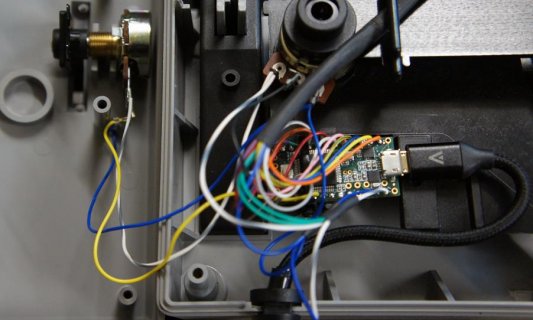
I got my Teensy flight yoke and pedals project working... it's not totally cleaned up or anything yet, so I'll probably do that this weekend and post it... but here's a quick preview.

I connected the wires, then removed the original PCB and installed the Teensy in its place. For all the pots, I connected the 3rd (previously unused) pin to GND, so pot outputs a voltage relative to the position, and can be connected directly to the analog pins.

yoke_w_teensy.jpg

pedals_added_wires.jpg

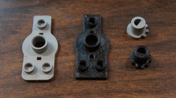
The pots in the yoke all moved over the full range (the pitch and roll both have a trim adjustment), though the pedals were slightly off. Neither of the toe brakes, nor rudder would go down to 0, and would top out at max scale before reaching the stopper. Rather than fixing it in software, I decided to 3D print replacement gears with the teeth rotated by a few degrees to get full scale min to max for the toe brakes, and a replacement pot bracket rotated by a few degrees to get it near center when resting, and full scale from left to right rudder inputs. I'd be glad to share those files if anyone's interested (though your degree adjustment amount may be different than mine).

printed_parts.jpg

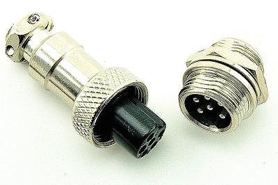
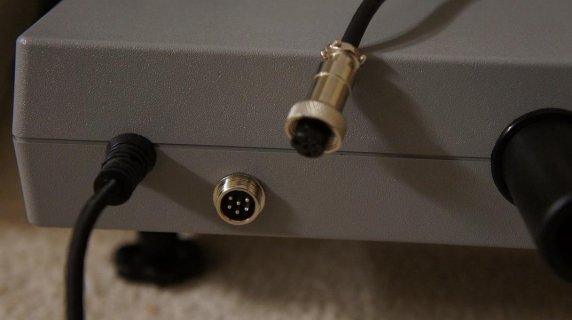
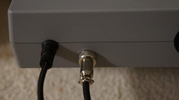
I also drilled a hole in the back of the yoke (and my HOTAS) for the rudder pedal connector. I decided to go with a GX12 connector... though I had to order them from China (I didn't have any of the 6-pin connectors in my parts bin), so I don't have it installed yet (I just temporarily stuck the wires through the hole and installed a 0.1" connector).

connector.jpg

DogP
 
I'll jump in on this thread.

I'm working on converting my old gameport CH devices (F-16 Fighterstick, Pro Throtte, Pro Pedals) into one big device using a Teensy 3.2. My plan is to use the existing DB15 cables/connectors and build a separate box to house the Teensy. I've already finished rewiring the three devices by adding ground connections to the pots and disconnecting the existing connectors to the pcb and shunting the button connectors directly to available pins. The stick and the throttle each use a button matrix so I'd suspect your yoke does as well.

As far as circuit prototyping and programming, I've made it as far as verifying that I have a valid circuit for reading the two matrices. I happened upon this thread because I decided I needed some guidance about the software design and to see what issues anyone else had encountered. I was concerned about jitter in the axes, but it looks like I just need to get some caps to include.

For the button matrix, I'm using pins 0-4 as the inputs (which go to both matrices), 5-8 as the outputs from the stick, and 9-12 as the outputs from the throttle. It's logically backward - I have the outputs set as INPUT_PULLUP, and set all of the inputs as output HIGH except the row I want to read. This way, a closed switch gets connected to the LOW input and drops the output to low as well. I also have a diode on each input to prevent other buttons from letting voltage bleed in from pressed buttons connecting the other inputs.

The design decision now is whether I just have to always strobe the matrices or if there's a better way using interrupts or something so I don't have to keep cycling the voltages on the input pins even though I've left it plugged in for three weeks/months/years and haven't touched it in almost as long. Is that going to be bad for the Teensy or any of the other parts involved over time? I have an engineering background, but I only had one EE class in college which only covered basic circuit design.

I can post more info about pinouts or anything else, if anyone's interested.

IMG_1403.jpg
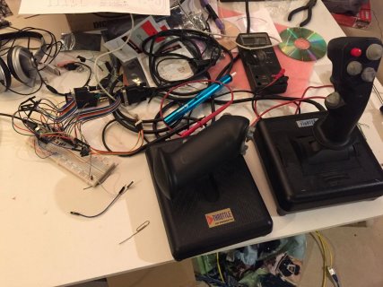
the before shot

IMG_1430.jpg
pedals (not pictured - the multiple attempts at reassembly, and when I gave up and took the pedals off)

IMG_1444.jpg
throttle

IMG_1453.jpg
stick

IMG_1405.jpg
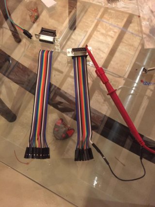
DB15 connectors I made using crimp connectors and half a cable from adafruit

IMG_1463.jpg
current proto status. I also used a cable off of a CueCat (anyone remember those?) to get at the PS2 keyboard pins on the throttle cable.


Scott
 
The gameport Y cable works when used in conjunction with the gameport to USB adapter. The adapter will pick up the cable as one controller and supports four axis, four buttons and four additional buttons of a hat switch. The game has to be able to assign the buttons and axis of each controller
 
Cool... looks like fun!

The stick and the throttle each use a button matrix so I'd suspect your yoke does as well.
Actually, no... on the yoke, the buttons/hats are simply a button with one side of the switch connected to ground.

I was concerned about jitter in the axes, but it looks like I just need to get some caps to include.
Some caps should help... or in my case, I set up the ADC with analogReadAveraging(32); , and also average the last 8 reads (so technically I'm averaging 256 samples). I also do a "dummy" read of a pin that's not changing between values, as I've noticed previous values slightly affect the following value (i.e. if you read the rudder immediately after the right toe brake, the rudder value will slightly differ depending on the toe brake value).

On another note... I finally got the connectors in, to connect the rudder pedals. I installed them, and it turned out nice. And I think I've pretty much got the code in a good state... gotta spend a little bit of time with it in FSX to make sure there isn't anything I want to change, but I'll post the project as soon as I can (probably in a week or so).

connector_unplugged.jpg

connector_plugged.jpg

Pat
 
@DogP, yeah, sorry, I see that you had the buttons figured out when I re-read it today.

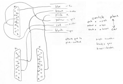
In case anyone's interested, here are my notes on the pedal wiring. One of my goals is to make this as reversible as possible, so I soldered a wire with a 0.1" female connector onto the same switch pin as the pink wire and then soldered the three ground wires from the pots to a 0.1" pin. With the switch in plane mode and the wires connected, I can get at all of the connections I need between the gameport and aux port connectors.

pedal_wiring.jpg
 
I registered after finding this thread. It's surprising to find people doing the same thing as me in April of 2016. I have almost the same setup as smmille1 (f16 Combatstick, pro pedals, pro throttle), and though I have a Teensy 2, I'm cheating by using a BU0836A. Despite that, I still have a ton of questions.

Initially I thought I'd just use the analog pins off the gameport connectors, but when I tried that the range of movement was a tiny square in the corner, so I tried wiring 3 pins to the pot directly and it's a vast improvement, full range of motion, no jitter.

On the stick axes, I see that you have a common ground and presumably common +5v, but I thought the middle terminal was shared across all axes in the original wiring.

My stick (F16 Combatstick) doesn't use a matrix, but it also has fewer buttons (14, or 18 if you count the 8 way hat as 8 buttons) than the Fighterstick.

I need to buy some diodes actually, since the bu0836 expects a matrix, this is all new stuff to me so I'm attempting to learn and figure things out as I go. 1N4148 seems like the thing to get.

It seems like there's not enough conductors in the existing DB15 cables. Am I missing something or is my cable bad?

From the throttle, there's only 9 wires in the DB15 connector that have conductivity (and 3 more in the keyboard connector) and I think that I need 9 for buttons and 2 (or 3?) for the axis.

For the stick, there's 10 wires, I need 6+3 for buttons so again I'm short for the axes.

I figured I'd get something like this http://www.l-com.com/d-sub-deluxe-b...male-male-cables-fully-populated-100-shielded twice as long as I need, then cut it in half and use one for the stick and one for the throttle, but if there's a way to do things with fewer conductors and use the existing cables, that'd be great.

Are you using quick disconnects to connect to the pots? It looks like it in your stick picture, I'd like to get some, but all I know is that they're .110 female connectors, and the original ones are maybe "Angled - 90°, Flag" like these http://www.digikey.com/product-detail/en/te-connectivity-amp-connectors/61549-1/A27769CT-ND/456857 ?

It seems you guys have already found or discovered all of the info I've found, but here's some stuff that I haven't seen posted:

http://www.kimdara.com/flipbox/ch_tech_pro_zoom.html
ftp://ftp.chproducts.com/pub/CHProducts_Game_Controller_Files/Wiring_Diagrams/Wiring

This thread from 2009 http://simhq.com/forum/ubbthreads.php/topics/2649989/aroubnd_vintage_CH_products_to was useful for me, but probably less useful to people here.

As an aside, in the process of opening these things up and poking around inside I'm delighted by how they're constructed. It's really nice to see devices that are designed to last forever and to be maintained when components wear out. Those manual pages would have saved me some time, but even so, it's pretty cool that the gameport pinouts are in the manuals at all.
 
I haven't had time to do much tinkering the past few weeks, but I can at least sneak in a reply.

On the stick axes, I see that you have a common ground and presumably common +5v, but I thought the middle terminal was shared across all axes in the original wiring.

Since the gameport wiring was just watching the resistance change, the polarity didn't matter and they had the +5V on the middle terminal, so I just swapped the two connections on every pot to move the input to the middle and then attached the ground to the open terminal.

My stick (F16 Combatstick) doesn't use a matrix, but it also has fewer buttons (14, or 18 if you count the 8 way hat as 8 buttons) than the Fighterstick.

I need to buy some diodes actually, since the bu0836 expects a matrix, this is all new stuff to me so I'm attempting to learn and figure things out as I go. 1N4148 seems like the thing to get.

It seems like there's not enough conductors in the existing DB15 cables. Am I missing something or is my cable bad?

I'm guessing they fed the buttons into a chip to encode them since that's more connections than a gameport can handle. I don't know what the possibility is that you could figure out what that chip's doing (maybe just chording the buttons?) and just use it if you're trying to use the existing cable.

From the throttle, there's only 9 wires in the DB15 connector that have conductivity (and 3 more in the keyboard connector) and I think that I need 9 for buttons and 2 (or 3?) for the axis.

This I can answer. If you're trying to use the existing cables, you'll have to get at the keyboard connections too. I used the cable off of an old CueCat (promo barcode scanner thing that I saved precisely because of the cable) but you could probably just get a PS2 extension cable and cut it in half to get a set of male and female connections. Here are my notes from the throttle wiring and how I jumpered it to bypass the logic board (ignore the CueCat wiring on the right):

throttle_wiring.jpg

For the stick, there's 10 wires, I need 6+3 for buttons so again I'm short for the axes.

I figured I'd get something like this http://www.l-com.com/d-sub-deluxe-b...male-male-cables-fully-populated-100-shielded twice as long as I need, then cut it in half and use one for the stick and one for the throttle, but if there's a way to do things with fewer conductors and use the existing cables, that'd be great.

Are you using quick disconnects to connect to the pots? It looks like it in your stick picture, I'd like to get some, but all I know is that they're .110 female connectors, and the original ones are maybe "Angled - 90°, Flag" like these http://www.digikey.com/product-detail/en/te-connectivity-amp-connectors/61549-1/A27769CT-ND/456857 ?

If you're ordering, I'd recommend getting the connectors. I scrounged existing wires with connectors that I already had, but didn't have quite enough. And of course, I ended up having to desolder one that I didn't have a connector for so I could disassemble and clean it.

As an aside, in the process of opening these things up and poking around inside I'm delighted by how they're constructed. It's really nice to see devices that are designed to last forever and to be maintained when components wear out. Those manual pages would have saved me some time, but even so, it's pretty cool that the gameport pinouts are in the manuals at all.

Compared to most things, it was a treat to be able to disassemble and reassemble something without having to pry or cut anything to get into it and then be able to put it back just like it was (minus the adhesive pads for the feet)!
 
I got my Teensy flight yoke and pedals project working... it's not totally cleaned up or anything yet, so I'll probably do that this weekend and post it... but here's a quick preview.

I connected the wires, then removed the original PCB and installed the Teensy in its place. For all the pots, I connected the 3rd (previously unused) pin to GND, so pot outputs a voltage relative to the position, and can be connected directly to the analog pins.

View attachment 6817

View attachment 6818

The pots in the yoke all moved over the full range (the pitch and roll both have a trim adjustment), though the pedals were slightly off. Neither of the toe brakes, nor rudder would go down to 0, and would top out at max scale before reaching the stopper. Rather than fixing it in software, I decided to 3D print replacement gears with the teeth rotated by a few degrees to get full scale min to max for the toe brakes, and a replacement pot bracket rotated by a few degrees to get it near center when resting, and full scale from left to right rudder inputs. I'd be glad to share those files if anyone's interested (though your degree adjustment amount may be different than mine).

View attachment 6816

I also drilled a hole in the back of the yoke (and my HOTAS) for the rudder pedal connector. I decided to go with a GX12 connector... though I had to order them from China (I didn't have any of the 6-pin connectors in my parts bin), so I don't have it installed yet (I just temporarily stuck the wires through the hole and installed a 0.1" connector).

View attachment 6819

DogP
Hi,

I doubt I won't get any feedback as this topic is quite old but ended up with an old set of Pro Pedals with gameport and I am in the process of converting them to USB using all the usefull information here. Getting the same problem with the pots slightly off. If you still have the STL for the 3D print replacement gears, I would be most grateful.
Many thanks,

Steeve
 
Back
Top