Teensy Audio: MCLK is not stable

Status
Not open for further replies.

caleb

Active member
Hello,
I love the Teensy audio board (just got it yesterday). However, the audio clock MCLK is not stable, which is the cause of some icky distortion.

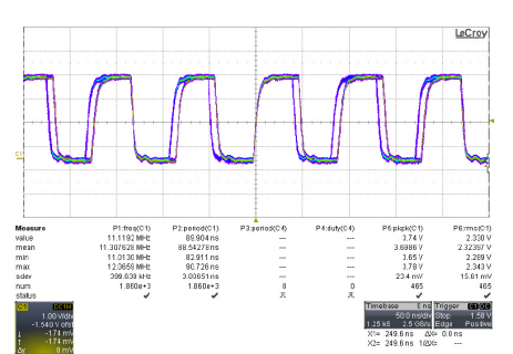
mclk.png

In the attached image, you can see the MCLK signal (pin 11), and clearly it has bi-modal duration with periods of about 90 ns and 82ns.

This definitely will not produce good sounding audio on record and playback.

Is there any way to make that clock stable? I have not looked into the hardware and software yet to see how MCLK is generated.


[edit:

I found that the clock is stable with clock speeds of 96MHz, 48MHz, and 24MHz.

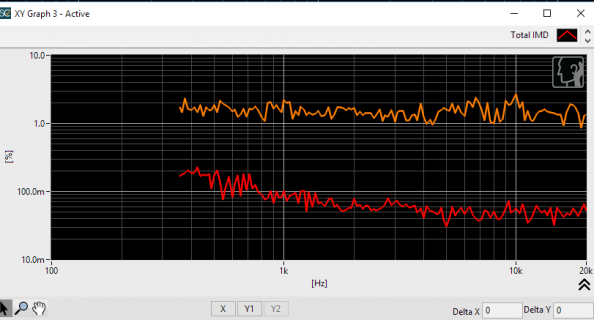
And I also found that somehow noise was injecting into my system previously. The IMD results for 96MHz and for 72 MHz are very similar, so audio performance doesn't seem to suffer too much with the weird MCLK.
]
 

Attachments

  • intermodulation.png
    intermodulation.png
    27.8 KB · Views: 221
Last edited:
In the attached image, you can see the MCLK signal (pin 11), and clearly it has bi-modal duration with periods of about 90 ns and 82ns.

This definitely will not produce good sounding audio on record and playback.

Why do you say so?
BTW the code is in "Audio\output_i2s.cpp" lines 254 ff
 
Why do you say so?
BTW the code is in "Audio\output_i2s.cpp" lines 254 ff

Well, just look at the trace I posted. Count the first rising edge in the center of the screen. The next rising edge is at one of 2 locations, either 90ns or 82ns later.

https://forum.pjrc.com/attachment.php?attachmentid=7242&d=1464279513

Edit: I just understood that your question is not about the bimodal MCLK, but rather why it won't produce good sound quality :) Sorry about that. You can just do a search for 'audio clock jitter' on google to see the issues. The MCLK should be very stable because it's what drives the entire audio conversion process. If it's not stable you'll get sidelobes in the converted data. BCLK can do whatever -- it doesn't matter

-Caleb
.
 
Last edited:
Trigger your scope on LRCLK (synchronous to the actual sample rate), for a better view of what the codec really sees.

Indeed the clock has different length cycles at 72 MHz, since there isn't a perfect divider to create it.
 
You can just do a search for 'audio clock jitter' on google to see the issues. The MCLK should be very stable because it's what drives the entire audio conversion process. If it's not stable you'll get sidelobes in the converted data.

Does the sampling not also depend on the way the ADC chip uses the MCLK? say, you have a stable dutycycle, say 66 to 33 %, and the ADC first divides by two before feeding the clock into conversion process, then the dutycyle is removed. I asked because I assumed you have insight into the functionality of the SGTL5000 an was simply curious.
 
Trigger your scope on LRCLK (synchronous to the actual sample rate), for a better view of what the codec really sees.

No, really, the codec sees MCLK independently of LRCLK. It's MCLK that drives the delta sigma converters, utterly independently of LRCLK. It's MCLK alone that matters here. LRCLK and BCLK can jitter wildly all over the place, but MCLK should be stable. LRCLK and BCLK must only be correct on average, whereas MCLK needs to be precise all the time. It's actually MCLK alone that drives the conversion rate, not LRCLK nor BCLK, which are there merely to extract the data from the codec, not to drive the conversion.

Perhaps a better method (though perhaps a bit more complex in software) to drive the clocking would be to drive the MCLK from a perfect divisor (just about any perfect divisor!) of F_CPU. Then use the PLL in the SGTL5000 to generate the rest of the clocking. Put the SGTL5000 into master mode, and the micro into slave mode. This will give a much more stable MCLK.


-Caleb
 
Does the sampling not also depend on the way the ADC chip uses the MCLK? say, you have a stable dutycycle, say 66 to 33 %, and the ADC first divides by two before feeding the clock into conversion process, then the dutycyle is removed. I asked because I assumed you have insight into the functionality of the SGTL5000 an was simply curious.

Duty cycle isn't critical (sort of). If it's 66% high/33% low, that's fine as long as you meet the timing requirements of the chip. It's the timing of the successive rising (or falling) edges that matter. However, I don't have any insight into the STGL5000. If it uses rising edges to clock the system, then the falling edge could jitter without consequence, as long as the rising edges are precise (though I'm not sure how you'd generate that clock!).
 
Perhaps a better method (though perhaps a bit more complex in software) to drive the clocking would be to drive the MCLK from a perfect divisor (just about any perfect divisor!) of F_CPU. Then use the PLL in the SGTL5000 to generate the rest of the clocking. Put the SGTL5000 into master mode, and the micro into slave mode. This will give a much more stable MCLK.

If you develop this code, and if it makes an audible or even measurable improvement in the SGTL5000 output, I'd love to merge it into the library.

I've personally spent a lot of time listening to the SGTL5000 output with the current code. It sounds very good. While I get what you're saying on a technical level, I'm a bit skeptical on whether it will really make any significant difference in real-world (audible or measurable with ordinary tools) performance.

Okay,
I measured the IMD using the built-in sine generators (so I didn't have to use the ADCs -- which are very noisy for my setup... will be a subject of another post), and the results say... the differences are measurable, but only barely.

First the sketch I used to generate a dual-tone signal that should show the IMD problems:
Code:
#include <Audio.h>
#include <Wire.h>
#include <SPI.h>
#include <SD.h>
#include <SerialFlash.h>

// GUItool: begin automatically generated code
AudioSynthWaveformSine   sine2;          //xy=173,146
AudioSynthWaveformSine   sine1;          //xy=182,108
AudioMixer4              mixer1;         //xy=363,121
AudioOutputI2S           i2s2;           //xy=526,109
AudioConnection          patchCord1(sine2, 0, mixer1, 1);
AudioConnection          patchCord2(sine1, 0, mixer1, 0);
AudioConnection          patchCord3(mixer1, 0, i2s2, 0);
AudioConnection          patchCord4(mixer1, 0, i2s2, 1);
AudioControlSGTL5000     sgtl5000_1;     //xy=256,218
// GUItool: end automatically generated code

void setup() {
  // put your setup code here, to run once:
  Serial.begin(9600);
  AudioMemory(12);
  sgtl5000_1.enable();
  sgtl5000_1.volume(.5); 
  delay(3000);
  Serial.print(AUDIO_SAMPLE_RATE_EXACT);
  // The sine-table used to create sine waves is 256 long.  Therefore for lowest distortion, 
  // we should make sure the sine rate is exactly sample_rate/2/256.
  sine1.frequency(AUDIO_SAMPLE_RATE_EXACT/2/256);    
  sine1.amplitude(.5);
  sine2.frequency(AUDIO_SAMPLE_RATE_EXACT/2/256*20);
  sine2.amplitude(.5);
}

void loop() {
  // put your main code here, to run repeatedly:

}

Since the generator uses a table, it's important to use frequencies that are exact steppings of the table, so fs/2/256 and multiples thereof.

The results are:

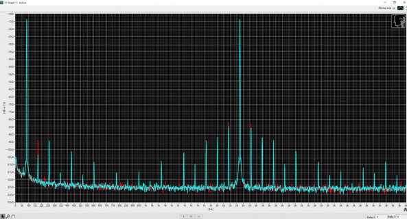
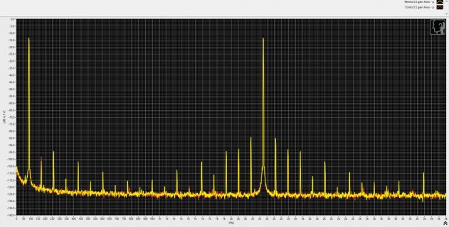
0.030 % THD at 96 MHz and 0.033 THD at 72 MHz.

The differences were tiny, but consistently different between the two.

imd on teensy.jpg

The cyan line shows the IMD (intermodulation distortion) with system clock at 96MHz, and red shows the distortion at 72 MHz.

Distortion products at about -70 dB from the fundamental is not great performance, but probably around what's expected for the SGTL5000.

My suspicion is that on a better DAC, the differences will become more apparent. It'll be interesting to see :)

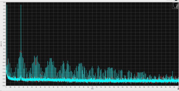
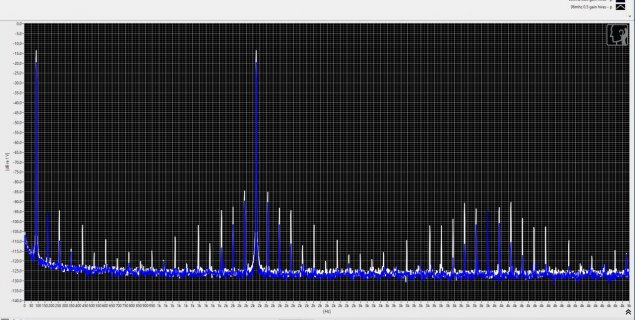
Here's the full spectrum for completeness.

imd2.jpg
 
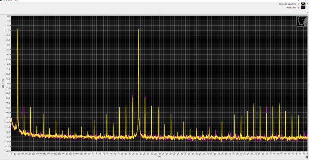
I checked your sine table, and at exact multiples of the fs/256 frequency, it was quite accurate. But I checked with the hires just to see, and the results are virtually identical. Very very minor differences:

This shows the 96MHz with the original sine, vs 96MHz with the hires sine:
imd3.jpg

And this shows the 96MHz hires sine vs 72 mhz hires sine:
imd4.jpg
Again, very tiny, inconsequential differences as far as I can see between 72 MHz and 96 Mhz.

I guess the MCLK jitter is just not a concern with this codec.


By bringing the gain down farther, the distortion goes down quite a bit, as seen in this graph. It shows 0.5 gain (nearly full scale output with 2 sine waves adding), vs 0.25 gain.
imd5.jpg

Code:
#include <Audio.h>
#include <Wire.h>
#include <SPI.h>
#include <SD.h>
#include <SerialFlash.h>

// GUItool: begin automatically generated code
AudioSynthWaveformSineHires sine_hires2;    //xy=160,237
AudioSynthWaveformSineHires sine_hires1;    //xy=166,187
AudioSynthWaveformSine   sine2;          //xy=173,146
AudioSynthWaveformSine   sine1;          //xy=182,108
AudioMixer4              mixer1;         //xy=363,121
AudioOutputI2S           i2s2;           //xy=535,122
AudioConnection          patchCord1(sine_hires2, 0, mixer1, 3);
AudioConnection          patchCord2(sine_hires1, 0, mixer1, 2);
AudioConnection          patchCord3(sine2, 0, mixer1, 1);
AudioConnection          patchCord4(sine1, 0, mixer1, 0);
AudioConnection          patchCord5(mixer1, 0, i2s2, 0);
AudioConnection          patchCord6(mixer1, 0, i2s2, 1);
AudioControlSGTL5000     sgtl5000_1;     //xy=240,381
// GUItool: end automatically generated code


void setup() {
  // put your setup code here, to run once:
  Serial.begin(9600);
  AudioMemory(12);
  sgtl5000_1.enable();
  sgtl5000_1.volume(.5); 
  delay(3000);
  Serial.print(AUDIO_SAMPLE_RATE_EXACT);
  // The sine-table used to create sine waves is 256 long.  Therefore for lowest distortion, 
  // we should make sure the sine rate is exactly sample_rate/2/256.
  sine1.frequency(AUDIO_SAMPLE_RATE_EXACT/2/256*6);    
  sine1.amplitude(0);
  sine2.frequency(AUDIO_SAMPLE_RATE_EXACT/2/256*20);
  sine2.amplitude(0);
  sine_hires1.frequency(AUDIO_SAMPLE_RATE_EXACT/2/256);    
  sine_hires1.amplitude(1);
  sine_hires2.frequency(AUDIO_SAMPLE_RATE_EXACT/2/256*20);
  sine_hires2.amplitude(1);
  mixer1.gain(2, .25);
  mixer1.gain(3, .25);
}

void loop() {
  // put your main code here, to run repeatedly:

}


-Caleb
 
By the way, did you consider generating a sine wave with a phasor?

Oops, posted too soon by accident:

By the way, did you consider generating a sine wave with a phasor?

If you store state as a complex number, then you can simply calculate the next sample my multiplying the state with a phasor.

Basically, it goes like this:
Code:
typedef struct {
   int32_t real;
   int32_t imag;
} complex_t;

typedef struct {
   complex_t state;
   complex_t phasor;
} sin_gen_t;

init(sin_gen_t *p, float freqeuncy, float sample_rate) {
     p->state->real = 1.0;
     p->state->imag = 0.0;
     w = frequency/sample_rate * 2 * pi;
    p->phasor->real = cos(w);
    p->phasor->imag = sin(s);
}

run_block(sin_gen_t *p, blocksize, int32_t *out) {
   for (i =0; i < blocksize; i++) 
   {
      p->state = p->state * p->phasor;  // complex multiply
      out[i] = p->state->real;
   }
}

The benefit is it's only 1 complex multiply per sample. The downside is that the phasor spirals in or out over time, so you need to renormalize state once in a while, which requires putting the length back to unity. (i.e. calculate length of state: l = sqrt(real**2 + imag**2), and set state = state/ l).

-Caleb
 
@Caleb .... that code is interesting! Should

Code:
p->phasor->imag = sin(s);
be

Code:
p->phasor->imag = sin(w);
Also, pardon my (further) ignorance, but how does

Code:
p->state = p->state * p->phasor;  // complex multiply
play out?? the state and phasor objects have two members, real and imaginary. Can * cope with that???

Also, does sin/cos use a lookup table? Is much gained over pahse accumlator approaches? (This is at the limits of my maths ability!!)
 
@Caleb .... that code is interesting! Should

Code:
p->phasor->imag = sin(s);
be

Code:
p->phasor->imag = sin(w);

Yes. I just typed that pseduo-code off the top of my head. :)

Also, pardon my (further) ignorance, but how does

Code:
p->state = p->state * p->phasor;  // complex multiply
play out?? the state and phasor objects have two members, real and imaginary. Can * cope with that???
Well, in c++, you can make a complex number type that does the complex multiply.

But, a complex multiply goes like this: to multiply c = a * b where a, b and c are complex numbers goes like this:

Break the a and b into their components, and calling 'j' the imaginary sqrt(-1), you get this:

Code:
a = Ra + j*Ia
b = Rb + j*Ib
c = a * b = (Ra + j*Ia) * (Rb + j*Ib)
          = (Ra*Rb) + (Ra * j*Ib) + (Rb * j*Ia) + (j*Ia * j*Ib)
          = (Ra*Rb - Ia*Ib) + j*(Ra*Ib + Rb*Ia)

so the real part of c is: (Ra*Rb - Ia*Ib)
and the imaginary part of c is: (Ra*Ib + Rb*Ia)

So, where did the minus sign come from?  It's because j = sqrt(-1), and j*j = sqrt(-1)*sqrt(-1) = -1!
Also, does sin/cos use a lookup table?
Not sure, but whatever it does, it should be pretty accurate

Is much gained over pahse accumlator approaches? (This is at the limits of my maths ability!!)

It definitely has an advantage over the lookup table version in that you can represent low frequencies accurately, which is pretty much impossible with a lookup table. In the case of the Teensy sin generator, it uses a table of 256 samples, which corresponds to a frequency of 44100/256 = 172.26 Hz.

what if you want to send a tone of 86.13 Hz? In that case the samples need to repeat twice before stepping. You could always do interpolation with the table based approach to help that though.

At even lower frequencies even interpolation really looses accuracy.

The hires sin generator is a neat approach, using taylor series. I haven't thought about them since college :) It looks like that will be quite accurate. It does take a fair number of operations to get to the answer, so there's the question of mips there. If mips is a non-issue, then the hires version seems just dandy. It has the benefit of not drifting in amplitude over time so it doesn't need to be renormalized.

So... long story short, I don't know if there is a benefit to a phasor approach over the hires version or not. somebody would have to take a close look and do some analysis. MIPS wise, I think it's lower than taylor series (4 multiplies, 2 adds per sample), as opposed to what looks like an 'if' plus 12 multiplies, plus a shift per sample. Accuracy wise, it's definitely more accurate than a table based approach.

Here is some python code for you to play with
Code:
from numpy import *
from pylab import *


fs = 44100.0
frequency = 101.1 # some oddball frequency not a perfect multiple of fs.
state = complex64(1.0 + 1j*0) # use 32-bit floats
# compute this many samples
n = 100000

#      cycles/second      2*pi radians    radians
# w = ----------------- * ------------ = --------
#      samples / second    cycle          sample
w = frequency/fs * 2 * pi

phasor = complex64(cos(w) + 1j * sin(w))
output = zeros(n, dtype=complex)
output[0] = state

for i in range(1, n):
    output[i] = output[i-1] * phasor  # <--- python is handling the complex multiply for me
plot(real(output), imag(output))
show()

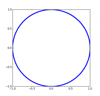
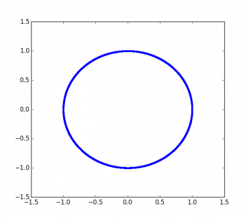
That produces a plot that looks like this:
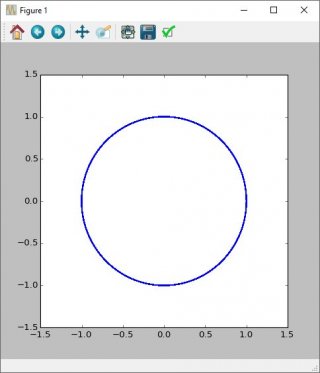
phasor1.jpg

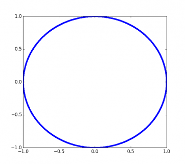
Which if you zoom in closely on the line, you'll see is not quite a perfect circle:
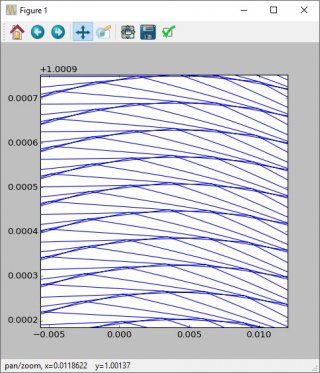
phasor2.jpg

Which is why you need to renormalize the length of the state vector back to unity once in a while. Perhaps once per block. Perhaps once per several blocks. With floating point you can obviously go a long time (100,000 samples) without renormalizing, but with fixed point, you need to renormalize more often.
 
Here's a modified version that can simulate different fixed point numbers (badly).
Code:
from numpy import *
from pylab import *


fs = 44100.0
frequency = 12001 # some oddball frequency not a perfect multiple of fs.
state = complex(1.0 + 1j*0)
# compute this many samples
n = 1000000

#      cycles/second      2*pi radians    radians
# w = ----------------- * ------------ = --------
#      samples / second    cycle          sample
w = frequency/fs * 2 * pi

phasor = complex(cos(w) + 1j * sin(w))
output = zeros(n, dtype=complex)
output[0] = state

digitize = float(1<<31)  # Simulate 32-bit ints
for i in range(1, n):
    o = output[i-1] * phasor
    #round to simulate 16-bits (or whatever value digitize represents)
    o = round(real(o)*digitize) + 1j*(round(imag(o)*digitize))
    o = o / digitize
    output[i] = o

print abs(output[0]), abs(output[-1])
plot(real(output), imag(output), ".")
show()

Here it is with no digitizing (doubles). Final length = 0.999999946968
phasor-double.png

And after 1 million samples at int32: final length = 0.999999946968.
I didn't realize 32-bit ints would be so accurate.
phasor-int32.png

And after 1 million samples at int16: final length = 1.00001380443
phasor-int16.png

So, it looks like you could even do this with 16-bit math and not have to renormalize very often.

-Caleb
 
You could always do interpolation with the table based approach to help that though.

The sine and other table-based code does indeed use linear interpolation.

At even lower frequencies even interpolation really looses accuracy.

Yes, but with the table covering down to 172 Hz, 86 Hz is reached with interpolating 1 sample between points, 57 Hz with 2 interpolated samples, and 43 Hz with 3 interpolated samples. While such low frequencies can be heard by humans or experienced as chest-thumping vibration, hopefully a small loss of accuracy isn't sonically very important.

The hires sin generator is a neat approach, using taylor series. I haven't thought about them since college :) It looks like that will be quite accurate. It does take a fair number of operations to get to the answer, so there's the question of mips there. If mips is a non-issue, then the hires version seems just dandy.

The main motivation for the hires sine was testing (supposedly) 24 bit DACs. So far, no such testing appears to have actually been done, but the digital data is there for the day anyone wishes to try. It's also meant to allow comparison to the table-based code, in cases where signal quality measurements are made and the round-off errors of the table need to be ruled out (or diagnosed) as a source of significant error.

While developing the Taylor series code, I discovered the 7th order case *exactly* matches the double precision float version compiled on Linux against the normal C library. It seems the C lib sin() function uses a 7th order Taylor series approximation.

So... long story short, I don't know if there is a benefit to a phasor approach over the hires version or not. somebody would have to take a close look and do some analysis. MIPS wise, I think it's lower than taylor series (4 multiplies, 2 adds per sample), as opposed to what looks like an 'if' plus 12 multiplies, plus a shift per sample. Accuracy wise, it's definitely more accurate than a table based approach.

If someone *really* wanted to do this, the contribution would probably be welcome. It may or may not be more efficient, probably depending on whether anyone goes to the trouble of mapping it onto the DSP extensions.
 
Last edited:
Status
Not open for further replies.
Back
Top