LPTMR on the Teensy 3.1/3.2/3.5/3.6

Status
Not open for further replies.

naylorjs

Member
I have a little project called the MMDVM. It supports the Arduino Due, the STM32F4xx series of chips, and now the Teensy. However I have a problem.

The software is required to clock an ADC very accurately, typically at 24 kHz or 48 kHz. It can use the internal clock, on the Teensy using the PDB, but that isn't accurate enough for my needs. It was enough to test the ADC, DAC and other code. The next stage was to clock the ADC from an external accurate (less than 1ppm usually) oscillator. According to example code and the data sheets this should be done using the LPTMR. However experiments trying this have not yielded successful results, it doesn't appear to trigger the interrupt.

The code can be seen at https://github.com/g4klx/MMDVM/blob/master/IOTeensy.cpp

To use the external oscillator the EXTERNAL_OSC symbol is defined, otherwise the internal oscillator is used.

So I have two questions:
1. What is wrong with my code?
2. Is it possible to use another pin rather than pin 13 so that the LED can live in peace?

Jonathan
 
I am not an expert in the LPTMR... But wonder where the ISR is set for the LPTMR?

I would expect that you would have the function: lptmr_isr

Defined in your code to overwrite the default ISR or you would use attachInterruptVector to set it.

My quick look at my spreadsheet for the T3.6 only shows pin 13
 
don't you have have to set PSR[PCS] to 3 to select external clock source for LPTMR
pin table shows LPTMR ALT on pins PTC5 or PTA19

Edit: PTC5 is pin 13, but PTA19 is crystal input, i think. sigh
 
Last edited:
chapter 47 (LPTMR) K66 ref manual says for PSR[PCR] 0 MCGIRCLK, 1 LPO, 2 ERCLK32K, 3 OSCERCLK_UNDIV (external ref clock) Teensy 3.1 ref manual, section 3.8.4.1 says same.

EDIT: OK you're right, I'll defer to Paul's example. I haven't tried external input (pulse counter mode), but i have LPTMR sketch that uses either LPO, 32khzOSC, or MICGIRCLK as timing sources (timer counter mode). And the external reference clock timing source is just the 16mhz crystal output.
 
Last edited:
well, you might try not setting interrupt (TIE), I think the hardware trigger will still work.
 
Thanks Manitou. I've updated my program and will inform one of the other guys to give it a run.

I'll report back.

Jonathan
 
Well it almost works. It's a lot better than before in the fact that it clocks, but doesn't match the PDB functionality yet. I'm wondering if it's now down to the ADC0 pre-trigger?

This is set for the PDB but not LPTMR0. I've not found a good description of what it does, or why it's needed, but I've now enabled it for the LPTMR0 and will see if that makes a difference.

Almost there though :)

Jonathan
 
i'm not sure what you mean. what i observed in my little sketch was that sample count was half what i expected. If i set CMR=1 and PWM frequency was 4800 hz, then i got 2400 ticks. so tick rate was frequency/(CMR+1)
 
What I meant to say is that although the changes you suggested made it work far better than it did before, it still wasn't working as well as with the PDB and the inaccurate oscillator. The whole point of the external oscillator is to make the sampling very accurate and therefore out perform the internal oscillator, which it didn't. The PDB code enabled the pre-trigger for the ADC, so I added the pre-trigger to the LPTMR also, which seemed to improve matters. I've also decremented the CMR value by one which will have a major effect on the performance also, since the sample rate will have been somewhat inaccurate with the previous CMR value.

Jonathan
 
FWIW, this may be circular nonsense, but with my sketch (PWM/23 to pin 13) @48khz (CMR 1), the long term LPTMR count shows an error of 24 ppm. I have measured the crystal on this T3.2 at about -19 ppm (with NTP or GPS), so that might? suggest the sketch/LPTMR is adding an error of 5 ppm? (48khz PWM is exact prescaler of 96mhz, so no discretization error). if i feed 48khz PWM into FreqCount library, it counts exactly 48000 for every 1s sample period... probably meaningless.

I obviously don't have a signal generator. If you feed your signal generator into my sketch, what does sketch report as measured frequency?
and if you feed your generator into a FreqCount library sketch?

or not.
 
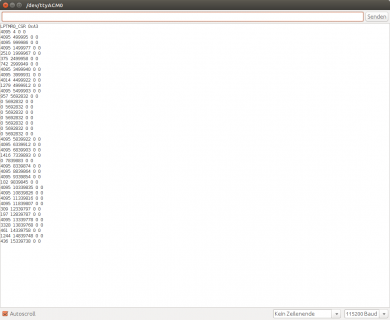
As one of the guys testing the stuff that naylorjs develops I put the above mentioned sketch onto my Teensy 3.6. Connected is the normally used external hardware board with 12MHz TCXO connected to Pin13. The result is:

Bildschirmfoto vom 2016-12-14 16-43-06.png
 
I can try that. The value in the first column is the ADC value. Why is that 4095 most of the time but drops on a regular basis?
 
I can try that. The value in the first column is the ADC value. Why is that 4095 most of the time but drops on a regular basis?

what do you have attached to A0 ? if it's floating the values usually are random around 300 or 400. if you ground A0, you should see 0's, if you
jumper A0 to 3.3v you should see 4095.

question: what is your 12 mhz generator set at? it looks like the sketch is saying input rate is 1mhz (since it reports 500khz with CMR 1)

EDIT: in your monitor listing, there is a sequence of 0 ADC values AND the ticks aren't advancing ??????
 
Last edited:
Ok. Putting A0 to GND yields

Code:
0 4673938 0 0
0 4673938 0 0
0 4673938 0 0
0 4673938 0 0

Wiring it to +3.3V:

Code:
4095 4674153 0 0
0 4674153 0 0
0 4674153 0 0
0 4674153 0 0

So just one glith to 4095 and back to 0 ...

TCXO is set to 12 MHz. Possbily the Pin 13 LED is interfering?
 
the ADC values will change only if the LPTMR (or PDB) is ticking. the output shows the tick value the same, so the ADC won't change. I reset the adcval to 0 in the loop().
I updated my sketch on github with the PDB fix (which i think you need in your library), and change to print output.

i can't explain why sketch measures 1MHz when you say you're driving pin 13 at 12MHz???

EDIT: in my sketch i set PWM freq to 12 mhz and LPTMR0_CMR = (12000000/24000)-1;
and sketch is reporting reasonable tick rates
...
ADC delta cumulative
1252 24000 8736078
978 24001 8760079
749 24000 8784079
990 24000 8808079

8808079/24000 = 367.003291
.003291/367 = 8ppm (which is about the crystal ppm error on the T3.6 i was using)
 
Last edited:
Ok, now it gives:

Code:
4095 499984 92009772
2189 499985 92509759
331 499984 93009747
2389 499985 93509735
4095 499985 94009723
4095 499985 94509711
4095 499985 95009699
4095 499985 95509687
4095 499985 96009675
2148 499985 96509663
0 499985 97009651
396 499984 97509639
4095 499985 98009627
4095 499985 98509614
4095 499985 99009602
1175 499985 99509591
2543 499984 100009579
4095 499985 100509567
4095 499985 101009555
4095 499985 101509544
3551 499985 102009531
848 499984 102509519
3352 499985 103009507
4095 499985 103509495
4095 499984 104009483
4095 499984 104509471
2352 499985 105009459
168 499985 105509447
594 499985 106009435
1390 499985 106509424
4095 499985 107009411
4095 499985 107509399
4095 499985 108009387
4095 499985 108509375
4095 499986 109009364
4095 499985 109509352
279 499985 110009340
962 499985 110509329
3608 499985 111009317
4095 499985 111509305
4095 499985 112009294
4095 499985 112509281
4095 499985 113009270
 
i'm still not sure why you're getting 499985 every second from 12mhz feed into pin 13. How about scaling the ADC sample rate to 24khz with
LPTMR0_CMR = (12000000/24000)-1;

and see what sketch reports
 
Okay that seems to work. Outputs 24kHz from what I can see:

Code:
LPTMR0_CSR 0x23
0 0 0
4095 24000 24000
4095 24001 48001
1379 24000 72001
1042 24000 96001
2778 24000 120002
4095 24000 144002
4095 24001 168003
4095 24000 192003
4095 24001 216004
181 24000 240004
485 24000 264004
1 24000 288005
799 24000 312005
4095 24001 336006
4095 24000 360006
4095 24001 384007
4095 24000 408007
4095 24000 432007
4095 24000 456008
1127 24000 480008
1705 24001 504009
3989 24000 528009

So we have to set the TCXO frequency explicitley?
 
well, your IOTeensy.cpp calculates the CMR prescale based on TCX0 frequency, so in my toy sketch you need to do the same (i've updated my github). With CMR fixed at 1 and 12mhz incoming, the max ADC rate (144Khz with F_BUS 60MHz and average 4, 576KHz with average 1) or ISR rate (less than 1 MHz) is probably the limiting factor, hence the 499985 numbers you were seeing.

The ppm error in your short run above 528009/24000= 22.000375 implies .000375/22 or about 17 ppm error, probably about same that you would see using PDB as the timer. the longer you let the sketch run, the more accurate the ppm estimate would be. the sketch could calculate ppm more precisely... though using micros() to calculate ppm will suffer from whatever the frequency error is in the teensy MCU crystal, typically 10 ppm, but varies per MCU and temperature.
 
Last edited:
Shall I let it run for a longer time then?
you could let it run for 10 or 20 minutes and note the last values printed. But it may not be useful to your needs since the first post in this thread talked about 1 ppm accuracy. if you 're trying to measure to 1 ppm, then the teensy clocks won't be adequate. you'd need to toggle a teensy output pin from the ADC ISR and measure that output frequency with some more accurate device.
 
Status
Not open for further replies.
Back
Top