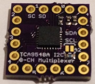
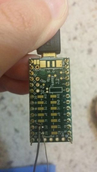
hello all,
For my project, I need to read data from 2 or more IMUs and although still I am not sure if it is possible, I want to read them with just one Teensy 3.2. I am using the code bellow to read one IMU and I use I2C. I think I should define the address for another IMU in functions "void Gyro_Init()" and "void Accel_Init()". But really don't know how (I am very new in programming Arduino and Teensy). Actually, I want to modify this code for reading two IMUs. Also, have no idea for two IMUs connections to Teensy (I can read one IMU and can connect it to Teensy).
Thank you so much.
#include <Wire.h>
#include <SoftwareSerial.h>
//12/20/2016
//Wire.setSDA(A3) and Wire.setSCL(A2)
#include <Wire.h>
#include <L3G.h>
#include <LSM303.h>
L3G gyro;
LSM303 compass;
double aRoll;
double aPitch;
double aYaw;
double ax;
double ay;
double az;
double vx;
double vy;
double vz;
int SENSOR_SIGN[9] = {1,1,1,-1,-1,-1,1,1,1};
double TIME;
#define GRAVITY 256
#define ToRad(x) ((x)*0.01745329252)
#define ToDeg(x) ((x)*57.2957795131)
#define Gyro_Gain_X 0.07
#define Gyro_Gain_Y 0.07
#define Gyro_Gain_Z 0.07
#define Gyro_Scaled_X(x) ((x)*ToRad(Gyro_Gain_X))
#define Gyro_Scaled_Y(x) ((x)*ToRad(Gyro_Gain_Y))
#define Gyro_Scaled_Z(x) ((x)*ToRad(Gyro_Gain_Z))
#define M_X_MIN -3506
#define M_Y_MIN -3473
#define M_Z_MIN -3764
#define M_X_MAX 3162
#define M_Y_MAX 3011
#define M_Z_MAX 2552
#define Kp_ROLLPITCH 0.02
#define Ki_ROLLPITCH 0.00002
#define Kp_YAW 1.2
#define Ki_YAW 0.00002
#define OUTPUTMODE 1
#define PRINT_ANALOGS 1
#define PRINT_EULER 0
#define STATUS_LED 13
float G_Dt=0.02;
long timer=0;
long timer_old;
long timer24=0;
int AN[6];
int AN_OFFSET[6]={0,0,0,0,0,0};
int gyro_x;
int gyro_y;
int gyro_z;
int accel_x;
int accel_y;
int accel_z;
int magnetom_x;
int magnetom_y;
int magnetom_z;
float c_magnetom_x;
float c_magnetom_y;
float c_magnetom_z;
float MAG_Heading;
float Accel_Vector[3]= {0,0,0};
float Gyro_Vector[3]= {0,0,0};
float Omega_Vector[3]= {0,0,0};
float Omega_P[3]= {0,0,0};
float Omega_I[3]= {0,0,0};
float Omega[3]= {0,0,0};
float roll;
float pitch;
float yaw;
float errorRollPitch[3]= {0,0,0};
float errorYaw[3]= {0,0,0};
unsigned int counter=0;
byte gyro_sat=0;
float DCM_Matrix[3][3]= {
{
1,0,0 }
,{
0,1,0 }
,{
0,0,1 }
};
float Update_Matrix[3][3]={{0,1,2},{3,4,5},{6,7,8}};
float Temporary_Matrix[3][3]={
{
0,0,0 }
,{
0,0,0 }
,{
0,0,0 }
};
float TIMENEW;
int i;
int y;
float MAG_X;
float MAG_Y;
float cos_roll;
float sin_roll;
float cos_pitch;
float sin_pitch;
float error=0;
float temporary[3][3];
float renorm=0;
float mag_heading_x;
float mag_heading_y;
float errorCourse;
static float Scaled_Omega_P[3];
static float Scaled_Omega_I[3];
float Accel_magnitude;
float Accel_weight;
int ic=0;
double Pmkf[4][4];
double xhat_old[4][1];
float Time;
void setup()
{
Serial.begin(115200);
Wire.setSDA(A3);
Wire.setSCL(A2);
I2C_Init();
//Wire.begin();
delay(150);
Accel_Init();
Compass_Init();
Gyro_Init();
delay(20);
for(i=0;i<32;i++)
{
Read_Gyro();
Read_Accel();
for(y=0; y<6; y++)
AN_OFFSET[y] += AN[y];
delay(20);
}
for(y=0; y<6; y++)
AN_OFFSET[y] = AN_OFFSET[y]/32;
AN_OFFSET[5]-=GRAVITY*SENSOR_SIGN[5];
for(y=0; y<6; y++)
delay(200);
timer=millis();
delay(20);
counter=0;
}
void loop()
{
ImuReadings();
Serial.println(aRoll);
Time=(float)millis()/1000;
}
//*******************************************************************
//EXTRA FUNCTIONS OUT OF LOOP
//*******************************************************************
void I2C_Init()
{
Wire.begin();
}
void Compass_Heading()
{
cos_roll = cos(roll);
sin_roll = sin(roll);
cos_pitch = cos(pitch);
sin_pitch = sin(pitch);
c_magnetom_x = (float)(magnetom_x - SENSOR_SIGN[6]*M_X_MIN) / (M_X_MAX - M_X_MIN) - SENSOR_SIGN[6]*0.5;
c_magnetom_y = (float)(magnetom_y - SENSOR_SIGN[7]*M_Y_MIN) / (M_Y_MAX - M_Y_MIN) - SENSOR_SIGN[7]*0.5;
c_magnetom_z = (float)(magnetom_z - SENSOR_SIGN[8]*M_Z_MIN) / (M_Z_MAX - M_Z_MIN) - SENSOR_SIGN[8]*0.5;
MAG_X = c_magnetom_x*cos_pitch+c_magnetom_y*sin_roll*sin_pitch+c_magnetom_z*cos_roll*sin_pitch;
MAG_Y = c_magnetom_y*cos_roll-c_magnetom_z*sin_roll;
MAG_Heading = atan2(-MAG_Y,MAG_X);
}
void Gyro_Init()
{
gyro.init();
gyro.writeReg(L3G::CTRL_REG4, 0x20); // 2000 dps full scale L3G_CTRL_REG4
gyro.writeReg(L3G::CTRL_REG1, 0x0F); // normal power mode, all axes enabled, 100 Hz L3G_CTRL_REG1
gyro.writeReg(L3G::CTRL_REG1, 0xFF);
}
void Read_Gyro()
{
gyro.read();
AN[0] = gyro.g.x;
AN[1] = gyro.g.y;
AN[2] = gyro.g.z;
gyro_x = SENSOR_SIGN[0] * (AN[0] - AN_OFFSET[0]);
gyro_y = SENSOR_SIGN[1] * (AN[1] - AN_OFFSET[1]);
gyro_z = SENSOR_SIGN[2] * (AN[2] - AN_OFFSET[2]);
}
void Accel_Init()
{
compass.init();
compass.enableDefault();
switch (compass.getDeviceType())
{
case LSM303::device_D:
compass.writeReg(LSM303::CTRL2, 0x18);
break;
case LSM303::device_DLHC:
compass.writeReg(LSM303::CTRL_REG4_A, 0x28);
break;
default:
compass.writeReg(LSM303::CTRL_REG4_A, 0x30);
}
}
void Read_Accel()
{
compass.readAcc();
AN[3] = compass.a.x >> 4;
AN[4] = compass.a.y >> 4;
AN[5] = compass.a.z >> 4;
accel_x = SENSOR_SIGN[3] * (AN[3] - AN_OFFSET[3]);
accel_y = SENSOR_SIGN[4] * (AN[4] - AN_OFFSET[4]);
accel_z = SENSOR_SIGN[5] * (AN[5] - AN_OFFSET[5]);
}
void Compass_Init()
{
}
void Read_Compass()
{
compass.readMag();
magnetom_x = SENSOR_SIGN[6] * compass.m.x;
magnetom_y = SENSOR_SIGN[7] * compass.m.y;
magnetom_z = SENSOR_SIGN[8] * compass.m.z;
}
void Normalize(void)
{
error= -Vector_Dot_Product(&DCM_Matrix[0][0],&DCM_Matrix[1][0])*.5;
Vector_Scale(&temporary[0][0], &DCM_Matrix[1][0], error);
Vector_Scale(&temporary[1][0], &DCM_Matrix[0][0], error);
Vector_Add(&temporary[0][0], &temporary[0][0], &DCM_Matrix[0][0]);
Vector_Add(&temporary[1][0], &temporary[1][0], &DCM_Matrix[1][0]);
Vector_Cross_Product(&temporary[2][0],&temporary[0][0],&temporary[1][0]);
renorm= .5 *(3 - Vector_Dot_Product(&temporary[0][0],&temporary[0][0]));
Vector_Scale(&DCM_Matrix[0][0], &temporary[0][0], renorm);
renorm= .5 *(3 - Vector_Dot_Product(&temporary[1][0],&temporary[1][0]));
Vector_Scale(&DCM_Matrix[1][0], &temporary[1][0], renorm);
renorm= .5 *(3 - Vector_Dot_Product(&temporary[2][0],&temporary[2][0]));
Vector_Scale(&DCM_Matrix[2][0], &temporary[2][0], renorm);
}
void Drift_correction(void)
{
Accel_magnitude = sqrt(Accel_Vector[0]*Accel_Vector[0] + Accel_Vector[1]*Accel_Vector[1] + Accel_Vector[2]*Accel_Vector[2]);
Accel_magnitude = Accel_magnitude / GRAVITY;
Accel_weight = constrain(1 - 2*abs(1 - Accel_magnitude),0,1);
Vector_Cross_Product(&errorRollPitch[0],&Accel_Vector[0],&DCM_Matrix[2][0]);
Vector_Scale(&Omega_P[0],&errorRollPitch[0],Kp_ROLLPITCH*Accel_weight);
Vector_Scale(&Scaled_Omega_I[0],&errorRollPitch[0],Ki_ROLLPITCH*Accel_weight);
Vector_Add(Omega_I,Omega_I,Scaled_Omega_I);
mag_heading_x = cos(MAG_Heading);
mag_heading_y = sin(MAG_Heading);
errorCourse=(DCM_Matrix[0][0]*mag_heading_y) - (DCM_Matrix[1][0]*mag_heading_x);
Vector_Scale(errorYaw,&DCM_Matrix[2][0],errorCourse);
Vector_Scale(&Scaled_Omega_P[0],&errorYaw[0],Kp_YAW);
Vector_Add(Omega_P,Omega_P,Scaled_Omega_P);
Vector_Scale(&Scaled_Omega_I[0],&errorYaw[0],Ki_YAW);
Vector_Add(Omega_I,Omega_I,Scaled_Omega_I);
}
void Matrix_update(void)
{
Gyro_Vector[0]=Gyro_Scaled_X(gyro_x);
Gyro_Vector[1]=Gyro_Scaled_Y(gyro_y);
Gyro_Vector[2]=Gyro_Scaled_Z(gyro_z);
Accel_Vector[0]=accel_x;
Accel_Vector[1]=accel_y;
Accel_Vector[2]=accel_z;
Vector_Add(&Omega[0], &Gyro_Vector[0], &Omega_I[0]);
Vector_Add(&Omega_Vector[0], &Omega[0], &Omega_P[0]);
#if OUTPUTMODE==1
Update_Matrix[0][0]=0;
Update_Matrix[0][1]=-G_Dt*Omega_Vector[2];
Update_Matrix[0][2]=G_Dt*Omega_Vector[1];
Update_Matrix[1][0]=G_Dt*Omega_Vector[2];
Update_Matrix[1][1]=0;
Update_Matrix[1][2]=-G_Dt*Omega_Vector[0];
Update_Matrix[2][0]=-G_Dt*Omega_Vector[1];
Update_Matrix[2][1]=G_Dt*Omega_Vector[0];
Update_Matrix[2][2]=0;
#else
Update_Matrix[0][0]=0;
Update_Matrix[0][1]=-G_Dt*Gyro_Vector[2];
Update_Matrix[0][2]=G_Dt*Gyro_Vector[1];
Update_Matrix[1][0]=G_Dt*Gyro_Vector[2];
Update_Matrix[1][1]=0;
Update_Matrix[1][2]=-G_Dt*Gyro_Vector[0];
Update_Matrix[2][0]=-G_Dt*Gyro_Vector[1];
Update_Matrix[2][1]=G_Dt*Gyro_Vector[0];
Update_Matrix[2][2]=0;
#endif
Matrix_Multiply(DCM_Matrix,Update_Matrix,Temporary_Matrix);
for(int x=0; x<3; x++)
{
for(int y=0; y<3; y++)
{
DCM_Matrix[x][y]+=Temporary_Matrix[x][y];
}
}
}
void Euler_angles(void)
{
pitch = -asin(DCM_Matrix[2][0]);
roll = atan2(DCM_Matrix[2][1],DCM_Matrix[2][2]);
yaw = atan2(DCM_Matrix[1][0],DCM_Matrix[0][0]);
}
float Vector_Dot_Product(float vector1[3],float vector2[3])
{
float op=0;
for(int c=0; c<3; c++)
{
op+=vector1[c]*vector2[c];
}
return op;
}
void Vector_Cross_Product(float vectorOut[3], float v1[3],float v2[3])
{
vectorOut[0]= (v1[1]*v2[2]) - (v1[2]*v2[1]);
vectorOut[1]= (v1[2]*v2[0]) - (v1[0]*v2[2]);
vectorOut[2]= (v1[0]*v2[1]) - (v1[1]*v2[0]);
}
void Vector_Scale(float vectorOut[3],float vectorIn[3], float scale2)
{
for(int c=0; c<3; c++)
{
vectorOut[c]=vectorIn[c]*scale2;
}
}
void Vector_Add(float vectorOut[3],float vectorIn1[3], float vectorIn2[3])
{
for(int c=0; c<3; c++)
{
vectorOut[c]=vectorIn1[c]+vectorIn2[c];
}
}
void Matrix_Multiply(float a[3][3], float b[3][3],float mat[3][3])
{
float op[3];
for(int x=0; x<3; x++)
{
for(int y=0; y<3; y++)
{
for(int w=0; w<3; w++)
{
op[w]=a[x][w]*b[w][y];
}
mat[x][y]=0;
mat[x][y]=op[0]+op[1]+op[2];
float test=mat[x][y];
}
}
}
void ImuReadings()
{
if((millis()-timer)>=5)
{
counter++;
timer_old = timer;
timer=millis();
if (timer>timer_old)
G_Dt = (timer-timer_old)/1000.0;
else
G_Dt = 0;
Read_Gyro();
Read_Accel();
if (counter > 5)
{
counter=0;
Read_Compass();
Compass_Heading();
}
Matrix_update();
Normalize();
Drift_correction();
Euler_angles();
#if PRINT_ANALOGS==1
//TIME = micros();
//TIMENEW = TIME/1000000;
aRoll=ToDeg(roll);
aPitch=ToDeg(pitch);
aYaw=ToDeg(yaw);
vx=(Gyro_Scaled_X(gyro_x));
vy=(Gyro_Scaled_Y(gyro_y));
vz=(Gyro_Scaled_Z(gyro_z));
ax=Accel_Vector[0]*9.81/256;
ay=Accel_Vector[1]*9.81/256;
az=Accel_Vector[2]*9.81/256;
//Serial.println(aRoll);
#endif
}
}


