Phone Compatible Game Controller Using Teensy 3.6

Status
Not open for further replies.

Lukef

Member
Hello,

So I am trying to create a game controller (with the same functionality of an XBox controller) that will plug into a phone (Android 7.x) via a micro USB connection. What I am wondering is which pins on my Teensy 3.6 would I connect all my inputs to? So, where would the joysticks plug into, the D-Pad, and all the other various buttons. Also, would I need to code anything for my phone to recognize the controller, or is that dependent on the game I am playing? I am very new to this but I do have an experienced engineer working with me so if it is possible to provide a basic answer for me and a more technical one that he would understand that would be great. If you can't do both then a technical one would be best.

Thanks so much!
Luke
 
Hello Lukef,

The Teensy has a gaming pad mode ; then you can configure which input does what as you can see in the example available with TeensyDuino. The next question is wether your phone will recognize the gaming pad as such or not, which is a good question I can currently not answer, but maybe Saturday if you have had no answer since then AND ask me again (like Friday evening). It works fine with several Linux distros I have tested though, so there are reasons to hope !

Ciao

Squeeek
 
Squeeek,

Thank you so much for your help!
One thing I was wondering is how would we configure the inputs? Maybe if you have a link to a page where it shows us how to do this? I've been looking around and can't find much... And the phone should receive the controller pretty well, or at least, so I've heard. We'll have to see when we get there.

Thanks,
Lukef
 
Hi Lukef,

As I mentioned in my previous post, I suggest you have a look at the Joystick examples in Teensyduino, where you can see how you might configure the pins ; basically, it is up to you, just make sure you use the analog pins for the analog sticks, then the rest can be used as digital I/O as you wish.

Sqk
 
One thing I was wondering is how would we configure the inputs?

I highly recommend using the Bounce library. It will save you from tremendous frustration caused by Teensy responding too quickly to mechanical chatter in the switches you use.

To get started, from Arduino make sure you have Teensy selected in the Tools > Boards menu. Then click File > Examples > Teensy > USB_Joystick > Buttons. The example has numerous comments and explains how the buttons should be connected, so hopefully it makes some sense?

Please, do yourself a huge favor by testing this with a regular PC first. Make sure you really have the buttons working and your PC recognizes and responds to it as a game controller.
 
You should also be aware that USB operates in 2 fundamentally different modes, called host and device. Like game controllers you can buy, Teensy operations in USB device mode.

If you're never heard of this before, please read (or just skim) chapter 4 from this USB spec. Here's a direct link to save you the time digging through www.usb.org to find it.

https://www.pjrc.com/teensy/beta/usb20.pdf

This document is huge, but chapter 4 is short and easy to read. It explains the key USB concepts and lingo. Especially if you need to ask USB questions, a basic familiarity with this USB jargon will really help you ask meaningful questions and understand the answers.
 
Paul and Squeeek,

Thank you guys so much for your help so far! I've got a bunch of articles and tutorials that me and my friend are going to be trying out soon so we'll see how that works out. I'll let you know if I have any other questions. If it all works out, I'll also post the results and how we got there.

Thanks again!
Luke
 
Hey guys,

Sorry this has been so late but we have been running into a couple of problems. So, for now we are just trying to get it working on PC before we try it on our phone (we actually bought a generic controller and plugged it in via micro USB and it worked so we are hopeful). Right now we also are just going with two analog joysticks just to figure things out. Here is our current setup:

7ks4iFCvPjpdcs1m9


(Can't tell if the pic worked... otherwise try https://goo.gl/photos/7ks4iFCvPjpdcs1m9 )

We have the joysticks hooked up to inputs 15, 16, 17, 18 (I believe those are analog inputs 1, 2, 3, 4 respectively). The pushbuttons that are on the joysticks are hooked up to inputs 0 and 1.
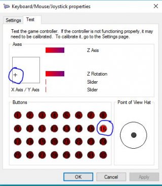
Initially, we had it hooked up running the example code provided by teensyduino and everything looked pretty good except that the left analog thought it was lower than it really was. So, while it was in the "deadzone" physically, it appeared to be halfway between the deadzone and all the way down when we looked at it from joy.cpl. Eventually we figured out that the actual joystick was the problem so now we have changed it out and got two brand new joysticks. Now the joysticks both work just great, although when I push the left joystick all the way to the left it reads that I am also pushing button 16? Whats with that?

But the main problem we have right now is that the pushbuttons on the joysticks are the wrong polarity. So, the Teensy is expecting them to pull down but the buttons pull up. How would I tell the Teensy to expect them to pull up?

We are on a pretty tight schedule, so I will keep looking around, but any help would be much appreciated.

Thank you!
Lukef
 
Hey Lukey, good to see you progressed !
What do you mean with "when I push the left joystick all the way to the left it reads that I am also pushing button 16" ? Which button 16 are you talking about ? Maybe you could provide your code as stated at the top of each page of this forum...? ;-)

As for reverting the state of a button, you could replace e.g.
Code:
Joystick.button(1, digitalRead(0));
with
Code:
Joystick.button(1, !digitalRead(0));
(the exclamation mark reverses a boolean state)

I hope this helps !

Sqk
 
Sqk,

Sorry, I missed the post your code part. But I don't know exactly which part to post... I am very new to coding and I know mostly web dev languages (HTML, CSS, and a bit of Python as well). Maybe this screenshot from joy.cpl will help?

JoystickRead.JPG

And as far as the reverse polarity, I just tried that but nothing changed. Check out my code... Is that what it is supposed to look like? Do I have to define what pins I have for each joystick button (0 and 1)?

void loop() {
// read 6 analog inputs and use them for the joystick axis
Joystick.X(analogRead(15));
Joystick.Y(analogRead(16));
Joystick.Z(analogRead(17));
Joystick.Zrotate(analogRead(18));
//Joystick.sliderLeft(analogRead(0));
//Joystick.sliderRight(analogRead(1));
Joystick.button(1, !digitalRead(0));
Joystick.button(2, !digitalRead(0));

Also, what is the Joystick.sliderLeft and .sliderRight used for? I did not know and they didn't seem to be doing anything so I just commented them out. I was thinking that those come from a joystick controller (like the first image in the teensyduino joystick example. I have a gamepad with the small thumb joysticks).
 
Hi again (that was quick, were you waiting for me...? :) )
I think you may have misused the analogRead function : you should pass the analog pin number (1, 2, 3, 4 in your case), not the DIO pin number (15, 16, 17, 18 in your case), although I agree that they are physically the same ; this may be the reason why the value is uncertain.
The sliders are extra analog inputs ; you correctly commented them out.
As for the buttons, I can see that you set DIO 0 to drive buttons 1 and 2, you probably want to use this instead :
Code:
Joystick.button(1, !digitalRead(0));
Joystick.button(2, !digitalRead([B]1[/B]));
I cannot see why button 16 would be triggered here, except if somewhere else in your code there is something like
Code:
Joystick.button(16, !digitalRead(0));
 
Sqk,

Thanks for replying so quick as well! And no, I'm not exactly waiting here. I am doing other research and I just get an email every time someone posts here and that shows up on my phone so I see it quickly.

Ok, so I changed those buttons around to read

Code:
Joystick.button(1, !digitalRead(0));   //the "0" is pin number?
Joystick.button(2, !digitalRead(1));

But nothing worked. I also tried doing just plain digitalRead() as opposed to !digitalRead() but still nothing. I have been looking through the code and can't really find anything that would be interfering, but then again I'm not skilled in this language. I'll post my code below and maybe you might see something that looks out of place?
Also, would this triggering of button 16 make any difference at all in games I play?

Sorry, I know this is a lot of code but I really don't know much about what I'm doing XD. Thank you so much for your help!


Code:
const int numButtons = 16;  // 16 for Teensy, 32 for Teensy++

void setup() {
  // you can print to the serial monitor while the joystick is active!
  Serial.begin(9600);
  // configure the joystick to manual send mode.  This gives precise
  // control over when the computer receives updates, but it does
  // require you to manually call Joystick.send_now().
  Joystick.useManualSend(true);
  for (int i=0; i<numButtons; i++) {
    pinMode(i, INPUT_PULLUP);
  }
  Serial.println("Begin Complete Joystick Test");
}

byte allButtons[numButtons];
byte prevButtons[numButtons];
int angle=0;

void loop() {
  // read 6 analog inputs and use them for the joystick axis
  Joystick.X(analogRead(1));
  Joystick.Y(analogRead(2));
  Joystick.Z(analogRead(3));
  Joystick.Zrotate(analogRead(4));
  //Joystick.sliderLeft(analogRead(0));
  //Joystick.sliderRight(analogRead(1));
  Joystick.button(1, !digitalRead(0));
  Joystick.button(2, !digitalRead(1));
  
  // read digital pins and use them for the buttons
  for (int i=0; i<numButtons; i++) {
    if (digitalRead(i)) {
      // when a pin reads high, the button is not pressed
      // the pullup resistor creates the "on" signal
      allButtons[i] = 0;
    } else {
      // when a pin reads low, the button is connecting to ground.
      allButtons[i] = 1;
    }
    Joystick.button(i + 1, allButtons[i]);
  }

  // make the hat switch automatically move in a circle
  angle = angle + 1;
  if (angle >= 360) angle = 0;
  Joystick.hat(-1);
  
  // Because setup configured the Joystick manual send,
  // the computer does not see any of the changes yet.
  // This send_now() transmits everything all at once.
  Joystick.send_now();
  
  // check to see if any button changed since last time
  boolean anyChange = false;
  for (int i=0; i<numButtons; i++) {
    if (allButtons[i] != prevButtons[i]) anyChange = true;
    prevButtons[i] = allButtons[i];
  }
  
  // if any button changed, print them to the serial monitor
  if (anyChange) {
    Serial.print("Buttons: ");
    for (int i=0; i<numButtons; i++) {
      Serial.print(allButtons[i], DEC);
    }
    Serial.println();
  }
  
  // a brief delay, so this runs "only" 200 times per second
  delay(5);
}
 
OK I can start getting something here...
Code:
const int numButtons = 16
--> you want to use 16 buttons... uh oh, 2 should suit you better !
Code:
Joystick.button(1, !digitalRead(0));
Joystick.button(2, !digitalRead(1));
You added this, right ? You do not need to, because it is already handled in the rest of the code with the allButtons and prevButtons arrays
I guess you could also remove everything related to the hat and angle
Is it any better now ?
 
Allright, so I changed the amount of buttons from 16 to 2 and that fixed that problem. I will be using about 10 buttons eventually, but for now I'll just leave that at 2.

As far as the joystick pushbuttons, they still aren't working. I commented out those two lines of code I added but still nothing. The hat I will also eventually use but commented just to keep them out of the way.
Maybe there is something in the allButtons and prevButtons that I am missing? I looked over that for a while but can't figure anything out...

Thanks,
Luke
 
Would you have a schematic of your electrical connections ? And possibly a link to the documentation of your joysticks ?
Normally, you should have at least :
one ground (connected to the ground of your Teensy 3.6)
one power supply (to connect to the 3V3 of your Teensy 3.6)
four analog channels (two axes per stick) connected to A1 to A4
two digital signals (for the stick buttons) connected to pins 0 and 1

A note for later, when you want to add the other stuff :
- DIO : use buttons 0 to 9 (or mode but make sure you do not go above pin 12 because 13 already has a LED which may cause you some trouble, and then we start eating up the analog pins), this is how it is configured in the code
- hat switch : the current code just rotates the hat switch 1° per cycle, this is probably not what you want ; check out what I wrote in this post as an example
 
Ok so we got the buttons working. Here's what we did:

We changed

Code:
pinMode(i, INPUT_PULLUP);

// WE CHANGED TO:

pinMode(i, INPUT_PULLDOWN);

and then, we also changed:

Code:
 // read digital pins and use them for the buttons
  for (int i=0; i<numButtons; i++) {
    if (digitalRead(i)) {
      // when a pin reads high, the button is not pressed
      // the pullup resistor creates the "on" signal
      allButtons[i] = 0;
    } else {
      // when a pin reads low, the button is connecting to ground.
      allButtons[i] = 1;
    }
    Joystick.button(i + 1, allButtons[i]);
  }

//WE CHANGED TO:

 // read digital pins and use them for the buttons
  for (int i=0; i<numButtons; i++) {
    if (digitalRead(i)) {
      // when a pin reads high, the button is not pressed
      // the pullup resistor creates the "on" signal
      allButtons[i] = 1;                                                 //Notice the number change
    } else {
      // when a pin reads low, the button is connecting to ground.
      allButtons[i] = 0;                                                 //Notice the number change
    }
    Joystick.button(i + 1, allButtons[i]);
  }

Thank you so much for you help. We are going to start adding in more buttons. If we have any more questions we'll let you know. I'll be sure to post some code here when I am done and whether it works with my phone or not.

Thank you so much!
Luke
 
Oh right, I forgot about that boolean inversion. Good job on your side, you did well ! Hope to get more good news from you soon ;-)
 
Thank you! Took a while but finally got it haha!

Ok, so now onto the buttons... My friend was saying that in the code we should be able to define what each button does (like how in a game one button might make your character "kick" while another makes him "jump"). He says that this way, the phone can differentiate between each button. I'm a little confused as to how to do that or even if we need to do that. I was thinking that all we had to do was go off the teensyduino joystick example where it shows you which is button 1, 2, 3, 4, etc. (based on the "Typical Gamepad Layout" image) and pretend button 1 goes to pin 1 (or maybe pin 0 to start off?). Or do we even need to do that?

I attached 4 more buttons to the teensy (and altered the expected button count in the code) and plugged it into my phone. Each button works, but does the exact same thing, select (or "tap" from a human perspective). Now I know there hasn't been much experience with phone controllers, but what about with computer? Do we need to define what each button does for computer, or simply plug them all in and the computer knows?

Thanks,
Luke
 
Hi Lukef,

I suggest you test everything with Windows first : check the buttons react properly, with the gamepad properties window you used two days ago. When it works properly there, start playing around with your phone (I do not know how it is supposed to react actually...)

Have a nice day

Squeeek
 
Hey guys,

Sorry for the delay, but I'm wondering how I would hook up the Hat to my Teensy (now 3.2). Like, which pins should I use? Analog or are the normal pins fine to use?
As far as defining which button is which, I saw this post and it looks like (to my unexperenced eyes) that he is defining which each pin is relative to which button it is. For example it looks like he has the "X" button (like that from an XBox controller) defined and hooked up to pin 6. Is that how I would define which each button is as opposed to just being a button?

Code:
Bounce GBZ_LEFT = Bounce(2, 10);
  Bounce GBZ_UP = Bounce(0, 10);  // 10 = 10 ms debounce time
  Bounce GBZ_DOWN = Bounce(1, 10);  // which is appropriate for
  Bounce GBZ_RIGHT = Bounce(3, 10);  // most mechanical pushbuttons
  Bounce GBZ_SELECT = Bounce(9, 10);
  Bounce GBZ_START = Bounce(8, 10);
  Bounce GBZ_X = Bounce(6, 10);
  Bounce GBZ_Y = Bounce(7, 10);
  Bounce GBZ_B = Bounce(5, 10);
  Bounce GBZ_A = Bounce(4, 10);
  Bounce GBZ_L = Bounce(10, 10);
  Bounce GBZ_R = Bounce(11, 10);

Thanks,
Luke
 
For example it looks like he has the "X" button (like that from an XBox controller) defined and hooked up to pin 6. Is that how I would define which each button is as opposed to just being a button?

Well, all the magic here is that it is yours to decide what causes what in your code :)
Here you define bounce objects, which are given appropriate names for the buttons you want ; they manage digital inputs AND manage the bounce effect for you, but you may also think you want (for whatever reason) to read analog inputs or touch sensors and activate the button only if the read value is above a certain threshold you would have to decide / experiment with.

The actual sending of the information "button X is pressed" to the PC is done with
Code:
Joystick.button(button_ID, boolean_value_depending_on_the_input)

Or you could use a random function so that the buttons have their own life. Not recommended for playing videogames though, might be a bit frustrating :)

As for which inputs to use for the hat switch, it is your choice too, also depending on your hardware. You may have four switches and use them to have four digital inputs driven to ground or to 3V3 (configure your digital inputs consequently, and you may also have to reverse the read state logic), or maybe you could have two analog inputs if you have an analog stick (one analog input per axis) - or a switches stick with resistors shunted by the switches to drive your analog input, but beware the short circuits you may create this way...

I am not sure I am so helpful with so many options but I want you to realise that :
1) you can do what you prefer
2) your hardware will lead you to different connections and software code

Have fun !

Squeeek
 
Sqk,

Thank you so much! I see how the bounce objects are defined how you like. As far as

Code:
Joystick.button(button_ID, boolean_value_depending_on_the_input)

if the button that I am defining is the same as the "X" button on an XBox controller and is connected to pin 0 on the Teensy, would I do this:

Code:
Joystick.button(X, 0)

What I am asking is how do I know what the button ID is for each button? I want to emulate an XBox 360 controller. Would I simply replace button_ID with what is written on them physically? For example (from XBox 360 controller), A, B, X, Y, LB, RB, LT, RT, UP, DOWN, LEFT, RIGHT, BACK, START (UP, DOWN, LEFT, RIGHT is for the hat) (these are all the buttons found on an XBox 360 controller).


Then to the hat, I have this one found on DigiKey and it has 5 buttons and a scroll wheel (not using the scroll wheel). I have them hooked up to pins 8, 9, 10, 11, 12. When I open joy.cpl, it reads them as just being buttons. How do I tell it that this is in fact a hat?

Thanks,
Luke
 
Your link to the hat does not point to a specific product but anyway you gave me enough details so I can explain a bit further.
So the first part is how you connect and read your data, this seems OK for now as far as I can see without your code (hint : check out what is written in red at the top of the forum page).
Now you have your bounce objects for your buttons, and maybe also for the directions of your hat (the fifth may be another button or unused, as you wish). As a simple example, let's imagine you have the debounced boolean states for your buttons X and Y, namely buttonX and buttonY (but you may name them as you wish), and also for the hat directions (buttonUp, buttonRight and so on).
1) for the buttons, you have to test which one corresponds to the X-box X and Y among IDs 1 to 16 ; beware that Joystick.X and Joystick.Y correspond to the analog axes (like left stick I guess), not to buttons. The buttons are numbered 1 to 16. So for example if you find out that button ID 2 is X and 5 is Y, you would have
Code:
Joystick.button(2, buttonX);
Joystick.button(5, buttonY);

2) for the hat, you need to check what I mentioned above from another post ; here is a copy-paste :
Code:
if (buttonUp){
   if (buttonRight) angle = 45;
   else if (buttonLeft) angle = 315;
   else angle = 0;
}
else if (buttonDown) {
   if (buttonRight) angle = 135;
   else if (buttonLeft) angle = 225;
   else angle = 180;
}
else {
   if (buttonRight) angle = 90;
   else if (buttonLeft) angle = 270;
   else angle = -1;
}
Joystick.hat(angle);

Of course you need to define variables and set values to the buttonX, buttonY, buttonTop, buttonRight and so on... depending on your inputs (bounce objects or digital read) before the code of this post.

The main confusion I guess is between the ID of a pin (for digital read or bounce) and the ID of a button as defined in the USB data exchanged. Technically, you could choose to swap two buttons when a third is pressed for example (again, not sure this is useful as is for a game controller, but I do have a project for a reconfigurable gamepad which might be interesting, once I get some time for it)
 
Status
Not open for further replies.
Back
Top