
mjs513
Senior Member+
Been quite for awhile while I was trying to get my next rover project going. Always wanted to do something with Obstacle Avoidance using a single cam with image processing to identify objects. Since I love my Teensy 3.5 figured I could do something with it but could not do it directly. Recently I found a OpenMV Camera that uses Micropython that does the Video/Image Processing algorithms for your ala OpenCV. I also found a project (https://bigfacerobotics.wordpress.com/2014/12/18/obstacle-detection-using-opencv/) that could be adapted to the openmv.
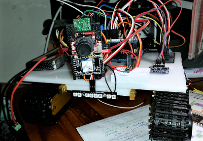
So I went ahead and used the OpenMV cam to detect obstacles and angular position in the frame and feed that info to the T3.5 which does the Obstacle avoidance stuff. It uses a single VL53L0X TOF sensor, a BN055 for orientation, a RC TX/Receiver and a RF for telemetry and commands. As in my other project it has an odometry module for relative tracking based on hall effect sensors on the motors (fixed the errors in my other code), a rudimentary, a control module using a RC transmitter and a manual mode for just sending motor commands. The odometry module receives manual commands individually in the format fx, bx, ly,ry where x is distance you want to travel in cm's and y is the relative angle you want to turn.
Most of the challenges I have right now is with the OpenMV, and getting the right algorithm and settings, it uses a OV7725 CCD. The firmware for it is still evolving and getting better. The obs is based off a modified vfh/bubble alogithm is the camera can not detect edges. Happens if it is too close to a wall. I use the VL53 sensor to get distances.
Anyway, a couple of other things I wanted to try was to get the T3.5 to do some image processing on its own, which I think I could get it do in a rudimentary way, based on a saved image. Unfortunately, the camera I selected for that piece, was a Arducam but I am having issues with that which I posted else where.
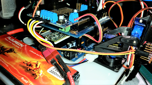
Oh, almost forgot it uses a custom breakout board for the T3.5 that puts it on a mega footprint and a custom expansion IO expansion shield with lots of pins and corresponding power and ground pins. It also uses a Adafruit Motor shield V2.
If anyone has any ideas for enhancements please let me know.
Here are a couple of photos:
So I went ahead and used the OpenMV cam to detect obstacles and angular position in the frame and feed that info to the T3.5 which does the Obstacle avoidance stuff. It uses a single VL53L0X TOF sensor, a BN055 for orientation, a RC TX/Receiver and a RF for telemetry and commands. As in my other project it has an odometry module for relative tracking based on hall effect sensors on the motors (fixed the errors in my other code), a rudimentary, a control module using a RC transmitter and a manual mode for just sending motor commands. The odometry module receives manual commands individually in the format fx, bx, ly,ry where x is distance you want to travel in cm's and y is the relative angle you want to turn.
Most of the challenges I have right now is with the OpenMV, and getting the right algorithm and settings, it uses a OV7725 CCD. The firmware for it is still evolving and getting better. The obs is based off a modified vfh/bubble alogithm is the camera can not detect edges. Happens if it is too close to a wall. I use the VL53 sensor to get distances.
Anyway, a couple of other things I wanted to try was to get the T3.5 to do some image processing on its own, which I think I could get it do in a rudimentary way, based on a saved image. Unfortunately, the camera I selected for that piece, was a Arducam but I am having issues with that which I posted else where.
Oh, almost forgot it uses a custom breakout board for the T3.5 that puts it on a mega footprint and a custom expansion IO expansion shield with lots of pins and corresponding power and ground pins. It also uses a Adafruit Motor shield V2.
If anyone has any ideas for enhancements please let me know.
Here are a couple of photos:
")