Teensy 3.6 whit 74hc595 - Pinout and power

Status
Not open for further replies.

Lenogi

Active member
Hi,
Sorry for my poor English.
I don't have much experience in electronics and I'm afraid of damaging the Teensy.
My project only receives power from the USB port.
I read a lot about the 74hc595 and the ShiftPWM Library, but I'm still in doubt where to connect on the Teensy 3.6.
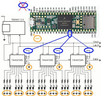
I marked in the picture my doubts.
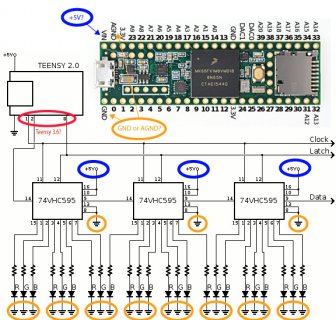
diagrama2.jpg


To start, I will do the tests only using 8 RGB LEDs, but in the final design, will be 9 RGB LEDs and 27 single color LEDs.
All ON most of the time.
Does the teensy 3.6 support this amount of consumption? Am I going to do any damage to the board?

Thanks
 
The 74hc595 will not draw power from the Teensy over the data, latch, and clock lines. And the Vin pin is (if you did not cut the trace) directly linked to the Vusb which gets the 5V from the computer. So, the question is, how many LEDs can be fed by the computer's USB port. The current through a LED depends on the series resistor (and, within certain limits, on the desired brightness), but lets roughly estimate an average of 18mA per LED. The computer's USB port might source 500mA (this is the USB specification). The Teensy itself will draw about 50mA, so that there are 450mA left for the LEDs. Divided by 18, you get 25 LEDs (or 8.3 RGB LEDs since these are 3 in one) which can be lit at the same time.
 
The 74hc595 will not draw power from the Teensy over the data, latch, and clock lines. And the Vin pin is (if you did not cut the trace) directly linked to the Vusb which gets the 5V from the computer. So, the question is, how many LEDs can be fed by the computer's USB port. The current through a LED depends on the series resistor (and, within certain limits, on the desired brightness), but lets roughly estimate an average of 18mA per LED. The computer's USB port might source 500mA (this is the USB specification). The Teensy itself will draw about 50mA, so that there are 450mA left for the LEDs. Divided by 18, you get 25 LEDs (or 8.3 RGB LEDs since these are 3 in one) which can be lit at the same time.

Thank you
This helps a lot!!

Now I just need to know, based in the scheme (Teensy 2), which are the corresponding pins (data, latch, and clock) in teensy 3.6.
 
I thought it best not to open another topic because it's still the same subject.
I'm trying to use the ShiftPWM with the Teensy 3.6.
I did the setup using three 74hc595 as shown on the site ( https://www.pjrc.com/teensy/td_libs_ShiftPWM.html ). I rebuild several times the circuit breadboard, changed the shift registers and the same problem happens.
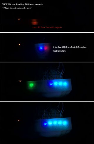
Only the first shift register works using the example File > Examples > ShiftPWM > ShiftPWM_RGB_Example. The other two light up randomly or are constantly On.
I kept the same mount on Breadboard, but I connected an Arduino Uno and everything worked perfectly.
What could be wrong?
 
the URL you note says On Teensy LC, 3.0, 3.1, 3.2, 3.5, 3.6, SHIFTPWM_NOSPI must be defined.
did you do that?

maybe look at https://forum.pjrc.com/threads/42018-ShiftPWM-problem

Hi manitou,
Thanks for the link. I´m using 74HC595N

Define SHIFTPWM_NOSPI is just remove "//" from the example code, right?

Code:
// ** uncomment this part to NOT use the SPI port and change the pin numbers. This is 2.5x slower **
#define SHIFTPWM_NOSPI
const int ShiftPWM_dataPin = 11;
const int ShiftPWM_clockPin = 13;
 
Are you using the latest ShiftPWM library? what version of IDE and teensyduino are you using? as the URL discussed, there was a speed problem with teensy vs AVR/UNO mcu's. Latest library should have fixed the problem, though you could do as we did early on in that URL, replace digitalWriteFast() with digitalWrite()
 
Are you using the latest ShiftPWM library? what version of IDE and teensyduino are you using? as the URL discussed, there was a speed problem with teensy vs AVR/UNO mcu's. Latest library should have fixed the problem, though you could do as we did early on in that URL, replace digitalWriteFast() with digitalWrite()

Teensyduino 1.41

PaulStoffregen/ShiftPWM
https://github.com/PaulStoffregen/ShiftPWM?files=1

replace digitalWriteFast() with digitalWrite() in ShiftPWM.h

No results :(
 
So not even the first shift register is working when using digitalWrite()?

The first shift register still working and the other two still weird.


maybe attach photos of your wiring with the T3.6

Wiring is correct.

Teensy > 74HC595
13 - 11
11 - 14
8 - 12

any chance you have more than one copy of shiftPWM lib on your machine? (what OS are you running)

That's interesting...
Where should I look?
If there's more than one, what should I do? Which one should I delete?
I´m using Windows 10 Pro x64

Thanks for help!
 
You risk to fry the Teensy's 3.3V voltage regulator! It is not designed to deliver enough power for so many LEDs. The circuit should normally work the same when powered with 5.0V, at least when using 74HC595 since the HC series consider every voltage > 2.0V as logical HIGH which allows to drive these with 3.3V signals from the Teensy, but to power them (and the LEDs) with 5V.

But I see on your schematic that you are using a 74VHC595 which needs 3.85V as logical HIGH when powered with 5.0V. WHY??? That's a huge design/engeneering error and obviously, you did not study the data sheet thoroughly.

There are two ways to solve that: 1. replace the 74VHC595 by normal 74HC595 or 2. keep the 74VHC595 and add a separate 3.3 voltage regulator to power them.
 
Hi,
I´m using three 74HC595.
I took the schematic of the site just to illustrate the pins connection.
Should I reconnect the circuit on the Vin pin and lower the voltage with a resistor?
 
Hi,
I´m using three 74HC595.
I took the schematic of the site just to illustrate the pins connection.
Should I reconnect the circuit on the Vin pin and lower the voltage with a resistor?


The T3.6 3v3 pin is rated at 250ma, so check your LEDs forward voltage and the resistors you are using with the LEDs to see what your power consumption is. 10ma per LED with 24 LEDs is cutting it too close with all LEDs on full power.
 
Interesting... As I wrote, you'd need to add a 3.3V >500mA (to be sure) low drop regulator between the Vin pin and the 595 supply rail. A resistor is not ok to lower the voltage in that place because that lowering will depend on the varying amount of current drawn by the LEDs and thus not give a stable voltage. That's Ohm's law.
 
The T3.6 3v3 pin is rated at 250ma, so check your LEDs forward voltage and the resistors you are using with the LEDs to see what your power consumption is. 10ma per LED with 24 LEDs is cutting it too close with all LEDs on full power.

I´m using 470 Ohm resistors for LEDs
 
Although 470R resistors *might* probably limit the current enough, it’s neither good practice nor clean engineering what you are doing here. What hinders you from adding a separate voltage regulator for the HC595 and LED sub circuit without exposing the expensive Teensy 3.6 to an unnecessary risk?
 
Although 470R resistors *might* probably limit the current enough, it’s neither good practice nor clean engineering what you are doing here. What hinders you from adding a separate voltage regulator for the HC595 and LED sub circuit without exposing the expensive Teensy 3.6 to an unnecessary risk?

I don't know much about electronics, but I'm learning from the tutorials.
My goal is a specific MIDI controller.
I'm testing the features separately to detect problems. I followed the layout presented on the site because I thought it was the right thing to do.
 
I think 74HC595 is the wrong chip for this application. It has to do with the minimum input high voltage for 74HC595 pins.
The minimum input voltage is calculated with 0.7 * Vcc. With 5V supply, the input voltage should be > 3.5V but the max output from a Teensy 3.6 is 3.3V.

74HCT595 (Nexperia/ Diodes inc.) or 74AHCT595 (Texas Instruments) is the recommended type. The minimum input high voltage for these is 2.0V.
 
Status
Not open for further replies.
Back
Top