CV connection without ground?

Status
Not open for further replies.

jidagraphy

Active member
Short version :
Generating DC voltage from the teensy board and connecting it directly to a 3.3v modular system (Volca Modular) *SEEMS* to work - literally just a jumper cable to a CV input of the external system, without any ground provided. But why does it work? and is it okay to use it like this?


Long version :

Hey.
So I've got a Korg Volca Modular. It's just a cute toy instrument version of a modular system, that uses jumper cables and operates in 3.3v. So I thought - Teensy is 3.3v, so why not connect my teensy onto the volca and I can control it better?

My initial thoughts were to just connect my teensy's output voltage to the volca via jumper cables but then I realised I can't just output voltages from a system to another without ground, and expect it to work. But I did. And it worked. At least the Gate CVs - haven't tested out Pitch CVs yet.

From what I understand, how we measure voltage is the *difference* between one end and the ground right? And thus normal Eurorack patch cable would have CV tip and Ground ring.

But what I'm doing is literally just connecting a pin on the teensy to a pin on the volca and its working. Weird thing is, when I operate the volca on 6AA battery instead of a power adaptor, it stops working. But it worked again when I tried plugging in an 'empty' CV-in cable to the volca, that sends nothing but has ground connected to my teensy. So I *think* it's a ground issue but I still dont understand why it works when my volca is connected on a power adaptor, and if I shouldn't be doing this lol.

Can anyone clarify what's going on?


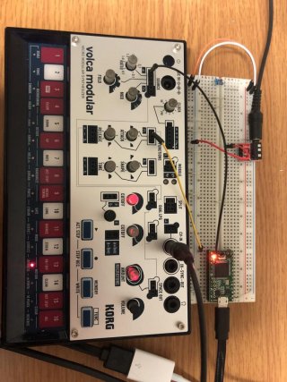
A working version of the system.
Teensy 3.2
Pin 13 into Volca's ADSR GATE
Pin A14 into Volca's pitch
An empty 3.5mm cable that only has ground connection of the teensy.
IMG_1821.jpg
 
Oh in case if anyone asks why I didn't make a normal CV out and connecting it to the CV in of the volca : I thought, because the volca operates in 3.3v already, I thought it'd work. and also :


CV–IN jack
This jack allows you to connect two external control voltage
sources to the volca modular. The left channel (tip) of the input is
clipped to +/-5V and scaled down to +/-3.3V, whereas the right
channel (ring) of the input expects a 1V/octave signal (0–+6V) and
converts it to the volca modular’s internal pitch offset voltage control
signal. Connecting a 3.5mm mono patch cable to this jack will result in
the same signal being applied to the CV and Pitch Offset inputs.

To do that, I would have to up the voltage of the teensy's 3.3v to 5v and 6v(for Pitch), just so it could bring it down to 3.3v again. And I dont know how to do that lol.
 
Don't do this, common the grounds always. It might appear to be working(*), but that's luck, not engineering! And be sure about the 3.3V thing
- perhaps add a 1k resistor in series to limit current should things not be as expected.

(*) One of the problems is that nearby electrical transients will be injecting directly into your Teensy pin this way, some day that will
fry the thing if the protection diodes are overwhelmed.
 
Don't do this, common the grounds always. It might appear to be working(*), but that's luck, not engineering!

Oh god I am scared. By 'commoning the ground' do you mean like what I've done with the empty CV in cable that connected to the ground of teensy? That seems to work when power adaptor isn't connected..
 
Oh god I am scared. By 'commoning the ground' do you mean like what I've done with the empty CV in cable that connected to the ground of teensy? That seems to work when power adaptor isn't connected..

Well you said "without ground" - but if they are already commoned its not a problem.
 
Well you said "without ground" - but if they are already commoned its not a problem.

Oh right, sorry I didn't even know what I did was commoning the ground, but I guess it makes sense. But just to clarify, you should not exchange voltages from pins between two seperate systems, without connecting ground?
So for example, if I wanted to connect two different teensys via some pins, i shouldn't just connect one output pin to an input pin, right? How would you share grounds with two teensys, by the way?

And also, a different question : when you previously said that I should add a resistor, how did you determine 1K would be a safe value??

Thank you MarkT! Really appreciate the help!
 
Oh right, sorry I didn't even know what I did was commoning the ground, but I guess it makes sense. But just to clarify, you should not exchange voltages from pins between two seperate systems, without connecting ground?
Yes and furthermore ground should connect first and disconnect last, just as with USB connectors. You haven't got a circuit till ground is connected, you
have an antenna.
So for example, if I wanted to connect two different teensys via some pins, i shouldn't just connect one output pin to an input pin, right? How would you share grounds with two teensys, by the way?
By connecting the grounds together. If they are already running from the same power supply then its already the case of
course.
And also, a different question : when you previously said that I should add a resistor, how did you determine 1K would be a safe value??
Its a rough guess - it will limit current to a few mA at worst, without limiting signal speed too much. If its a low bandwidth
signal you can use higher resistors. Ultimately a 'scope would answer the question more accurately by checking the rise
and fall times of the waveform. The higher the resistor, the more protection it can give, so 10k might be better in some
circumstances.
 
Yes and furthermore ground should connect first and disconnect last, just as with USB connectors. You haven't got a circuit till ground is connected, you
have an antenna.

By connecting the grounds together. If they are already running from the same power supply then its already the case of
course.

Its a rough guess - it will limit current to a few mA at worst, without limiting signal speed too much. If its a low bandwidth
signal you can use higher resistors. Ultimately a 'scope would answer the question more accurately by checking the rise
and fall times of the waveform. The higher the resistor, the more protection it can give, so 10k might be better in some
circumstances.

NICE!
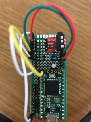
Thank you! With your help, I made a pretty little Audio utility board thingi
IMG_4541.jpg

I can connect Pin A14 DAC to a row of diode and 1k resistor to output CV, or use DAC as audio output and run it through a capacitor to the jack.
And of course, with the ground on the sleeve of the jack. I gave up on the direct teensy->volca jump cable setup. It does work with an empty 3.5mm connection only for the ground, but it just looks messy really. I ended up not amplifying anything, used 3.3v out and the resistor probably cut the voltage down significantly, but at the end, the volca had a calibration function, so I'm just using a few octaves and letting volca do the calibration for the Pitch CV.

I'm seeing if theres anything more I can do on this but there arent any more space left so pretty much done here I think.

Thank you MarkT! You've helped make a project come true :D
 
Status
Not open for further replies.
Back
Top