Happy New year!
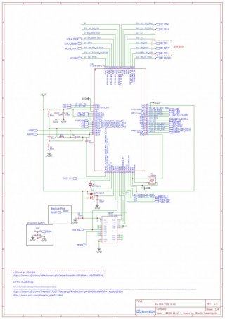
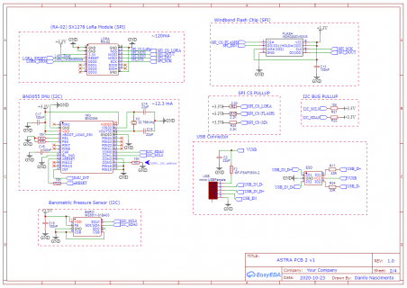
So I decided to make a custom PCB based on a Teensy 3.2. The goal of the PCB is to serve as Flight Computer so there are a few sensors and a LoRa Radio.
So the soldering part went alright I think for the first time doing SMT soldering. But then when I decided to Boot up (turn on the board) via USB It has "dead" nothing. I also reflowed the soldering and did multiple check to make sure no bridged connections where made. I also reviewed this troubleshoot guides and nothing. (found here)----> https://www.pjrc.com/store/ic_mkl02.html
I did make a second board with just the key Teensy 3.2 parts and connected to PC. It did the windows sound of some USB device connected and then disconnected.. I tried it again and same thing. The board didn't turn on /: and the Blue LED just flickered... Unfortunately I don't have a multimeter with me right now to check for shorts. or whether the Bootloader or the MCU is working properly.
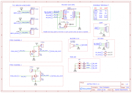
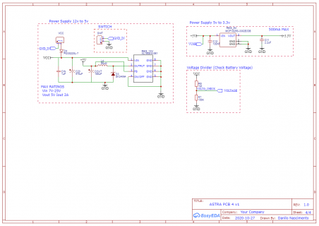
At the last resort I'm posting the schematic here and hopefully get some input. I will add the full schematic of the board.
Thanks in Advance


