
Teensy 3.1 + 4051 and ground (GND or AGND?)

Status
Not open for further replies.

nicolas_soundforce

Active member
Hi guys!

I am using about 3 CD74HC4051 chips for a MIDI controller project.
There seems to be quite some noise at the inputs of the ADC. I have to filter a lot to stabilize the signals (i am not registering any changes under 20 - on the scale from 0 to 1023).

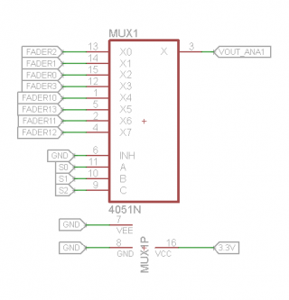
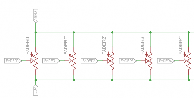
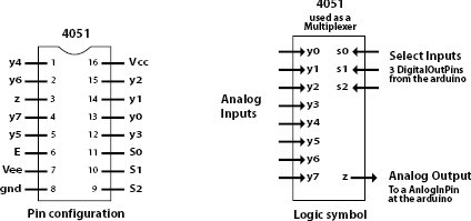
I realized I connected all the ground pins (pins 6/7/8) from the 4051s to the Digital Ground and not the Analog Ground of the Teensy. The potentiometers, on the other hand, are connected to AGND. May that be the reason I have so much noise ?

Thanks in advance!
4051_pins.jpg
Screen Shot 2014-09-22 at 9.50.09 PM.png
Screen Shot 2014-09-22 at 9.51.41 PM.png
 
You're doing it correctly. The '4051 pins connect to GND, the pots connect to AGND.

What is the pot resistance? Higher than 10K adds quite a bit of source impedance when the pot near the center of its range, so I'd suggest using 10K or less. But lower than 5K starts to really consume more power, and probably does little good.

If you can allow a little extra time between switching the mux and using analogRead(), you could try adding a small capacitor between the analog pin and AGND. That will lower the impedance at high frequency, which sometimes helps. A value like 470 pF or 0.001 uF is probably worth a try. The higher the capacitance, the longer it'll take for the pot to chance the voltage between the time you switch the mux and when you read it.
 
You're doing it correctly. The '4051 pins connect to GND, the pots connect to AGND.

What is the pot resistance? Higher than 10K adds quite a bit of source impedance when the pot near the center of its range, so I'd suggest using 10K or less. But lower than 5K starts to really consume more power, and probably does little good.

If you can allow a little extra time between switching the mux and using analogRead(), you could try adding a small capacitor between the analog pin and AGND. That will lower the impedance at high frequency, which sometimes helps. A value like 470 pF or 0.001 uF is probably worth a try. The higher the capacitance, the longer it'll take for the pot to chance the voltage between the time you switch the mux and when you read it.

Hi Paul,

Thank you for confirming that my circuit is correct. As I already ordered my PCBs for this project, I looked it solving this in the software.
Averaging 5 consecutive readings seemed to have fixed the noise problem.

Code:
 for (int i=0; i<5; i++){
      SmoothRead1 = SmoothRead1 + analogRead(VOUT_ANA1);
      SmoothRead2 = SmoothRead2 + analogRead(VOUT_ANA2);
      SmoothRead3 = SmoothRead3 + analogRead(VOUT_ANA3); 
      }
      
      MUX_ANA1_Channel[i] = SmoothRead1/5;
      MUX_ANA2_Channel[i] = SmoothRead2/5;
      MUX_ANA3_Channel[i] = SmoothRead3/5;
      SmoothRead1 = 0;
      SmoothRead2 = 0;
      SmoothRead3 = 0;
 
Status
Not open for further replies.
Back
Top