wwatson
Well-known member
- Joined
- Last seen
- Viewing forum list
- Messages
- 956
- Reaction score
- 56
Latest activity Postings About
-
-
 wwatson replied to the thread Call to arms | Teensy + SDRAM = true.What length wires are you using between the MCU and the display boards? WIth 10cm wires I could not get past 20Mhz when testing With an LCD and Micromod mounted to the same pcb with 2cm traces we got 24/30Mhz working. I am using the same length...
 -
wwatson replied to the thread Call to arms | Teensy + SDRAM = true.Thanks for the response. I wired up the dev board again and started testing with the baseline driver code I posted. It shows something is wrong in the dev board/MicroMod side of my code. No matter what I set the bus speed to loading the same...
-
-
wwatson replied to the thread Call to arms | Teensy + SDRAM = true.That's why I hope Rezo can go over the low level drivers I posted to make sure I am not missing something. I have a general idea of how FlexIO works but I might be missing some little details. Meanwhile I am wiring up the DevBoard again to test...
-
wwatson replied to the thread Call to arms | Teensy + SDRAM = true.I remember reading that. At this point I am not using the SDRAM at all with the display. It is strictly the traces between the 1062 MCU and the out side connectors of the board. Once that and DMA communications are solved then I can start testing...
-
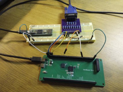
wwatson replied to the thread Call to arms | Teensy + SDRAM = true.@Rezo Here is the FlexIO2 pin usage I am using: FlexIO2------- Dev Board-------- ER-TFTM101-1 Pin 2:00 -----------> B0_00 -----------> /WR ---> 05 2:01 -----------> B0_01 -----------> /RD ---> 06 2:02 -----------> B0_02 -----------> 2:03...
-
wwatson replied to the thread Call to arms | Teensy + SDRAM = true.16 bits... lcdRegWrite(RA8876_CCR);//01h #if defined(USE_8080_IF) if(BUS_WIDTH == 16) { lcdDataWrite(RA8876_PLL_ENABLE<<7|RA8876_WAIT_NO_MASK<<6|RA8876_KEY_SCAN_DISABLE<<5|RA8876_TFT_OUTPUT24<<3...
-
wwatson replied to the thread Call to arms | Teensy + SDRAM = true.Not having good results with the SDRAM board and RA8876 in 16-bit 8080 mode. It's very unstable results:( Been playing with delays with no predictable results even at 2MHz. If I switch to 8-bit mode all of the examples in the Ra8876LiteTeensy...
-
wwatson replied to the thread Flashing 4.1 code on a board with a 4.0 bootloader chip.Thanks @Rezo - Will set it up in the AM. Bedtime...
-
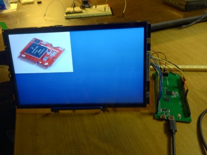
wwatson replied to the thread Call to arms | Teensy + SDRAM = true.Here is the SDRAM board and ER-TFTM101-1 TFT working in 8080 8-bit mode. It's a start:) Waiting on some info to try out 16-bit 8080 mode...
-
-
wwatson replied to the thread Flashing 4.1 code on a board with a 4.0 bootloader chip.Thanks - I do have the SDRAM board and TFT working in 8-bit mode now. Just fine tuning to see what kind of speed I can get...
-
wwatson replied to the thread Flashing 4.1 code on a board with a 4.0 bootloader chip.@Rezo - I see B0_13 is available on the SDRAM DEV board. It does not have a pin number associated with it. How would you setup B0_13 as FlexIO 2:13 without a pin number as being done like this: /* Basic pin setup */ pinMode(10, OUTPUT)...
-
wwatson replied to the thread Call to arms | Teensy + SDRAM = true.Just re-did it all and it's working :D Must have messed up on the wiring. Probably one off. It now works out of the box...
-
wwatson replied to the thread Call to arms | Teensy + SDRAM = true.Unless I missed something both B0_12 (35) and B0_13 (34) did not respond to a pin check with and LED connected to them. Just rechecked and they are not connected as well as pin B1_02 (36) and B1_03 (37). The only pin that is labeled as a T41 pin...
-
wwatson replied to the thread Call to arms | Teensy + SDRAM = true.Hi Defragster - I am using @jmarsh's SDRAM_EXTMEM library. I only had to modify one sketch that was setup for the T41. The rest of them work out of the box. The sketch that I modified was "flexio_vga.ino" which basically just changed the VSYNC...
-
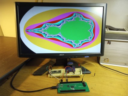
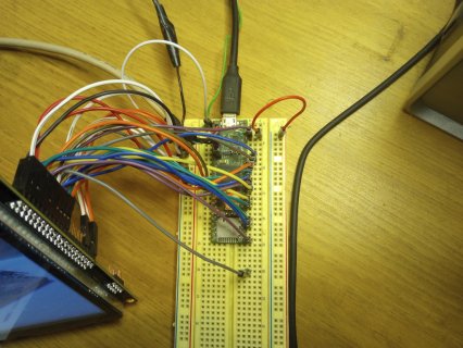
wwatson replied to the thread Call to arms | Teensy + SDRAM = true.@jmarsh - Tested the elcdif sketches. Impressive:D Did not realize the mandelbrot sketch was animated. Now to hook up the 10.1" LCD and test... EDIT: By the way the T41 on the breadboard is the first T41 I got from PJRC. It has the white...
-
-
wwatson replied to the thread Call to arms | Teensy + SDRAM = true.Thanks for the info and link above. I now have it working with external sdram. It seems to work ok up to 270MHz with a 1280x720 frame buffer. Excuse my shakey picture:) I still am not using double buffering like in your original sketch but it...
-
-
wwatson replied to the thread Call to arms | Teensy + SDRAM = true.First simple experiment on SDRAM board works. Adapted my 4-bit VGA library based on @jmarsh's driver to the dev board. Just had to change two pin defines for FlexIo2 for HSYNC and VSYNC which is used in several places in the FlexIO begin method...
-
-
The solder paste used on these boards are high temp 260c, it's actually very good solder. But to get something off you need a good iron and some flux. Or add a little more solder paste from a siringe (the latter is the best and easiest option)...
-
wwatson replied to the thread Call to arms | Teensy + SDRAM = true.Thanks, I do have that document. I ran the oneScanCaps.ino sketch and most of the frequencies had no errors. Interestingly enough 166MHz had one error. I am not sure which cap DQS has on the board. I can barely see it even with a magnifying...
-
wwatson replied to the thread Call to arms | Teensy + SDRAM = true.Just received the sdram development board today:D I ran through all of the test programs that I know about without a problem. I need to make sure I have all of the pinout info for this board. It is a version 4 board. I thought I would start out...
-
-
wwatson replied to the thread Buydisplay 10.1" TFT in parallel 8080 mode and Teensy FlexIO.Thanks, I'll take a look at it. So far it has been my lack of knowledge of FlexIO and DMA that has slowed me down but I'm starting to understand it more...
-
wwatson replied to the thread Buydisplay 10.1" TFT in parallel 8080 mode and Teensy FlexIO.Actually you still need these parts in place of gpioRead() and gpioWrite(): pFlex->setIOPinToFlexMode(12); // For /RD signal pFlex->setIOPinToFlexMode(10); // For /WR signal So here is a a version of lcdDataRead() that works...
-
-
wwatson replied to the thread Buydisplay 10.1" TFT in parallel 8080 mode and Teensy FlexIO.I am using this: pFlex->setClockSettings(3, 1, 0); // (480 MHz source, 1+1, 1+0) >> 480/2/1 >> 240Mhz and here is the FlexIO read setup: FASTRUN void RA8876_t3::FlexIO_Config_SnglBeat_Read() { #if defined(USE_MM) p->CTRL &=...
-
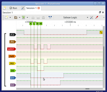
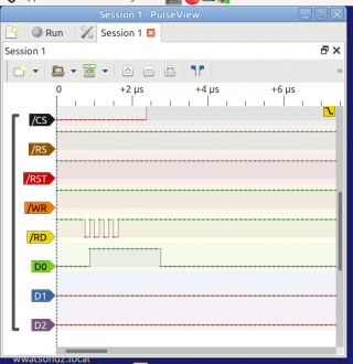
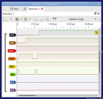
wwatson replied to the thread Buydisplay 10.1" TFT in parallel 8080 mode and Teensy FlexIO.I am trying to find the answer to why doing a FlexIO parallel read results in the /RD signal showing 4 pulses as apposed to the /WR signal showing just one pulse. I have looked all over the net and reference manual with no luck. It's probably...
-
-
wwatson reacted to TFTLCDCyg's post in the thread my SDfat code - good in 2017 but won't compile now? with
 Like.
In my case, I use IDE 1.8.19 because it is the version that does not give me errors with sketches that have many tabs. The IDE 2.x has given me a lot of headaches. In case of tracking down an error in the code it is easier, the excesses of help...
Like.
In my case, I use IDE 1.8.19 because it is the version that does not give me errors with sketches that have many tabs. The IDE 2.x has given me a lot of headaches. In case of tracking down an error in the code it is easier, the excesses of help... -
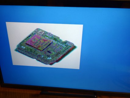
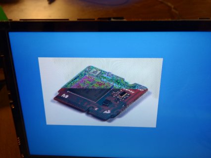
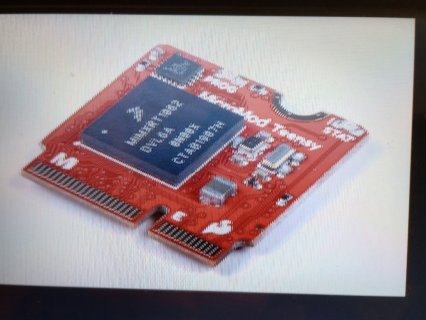
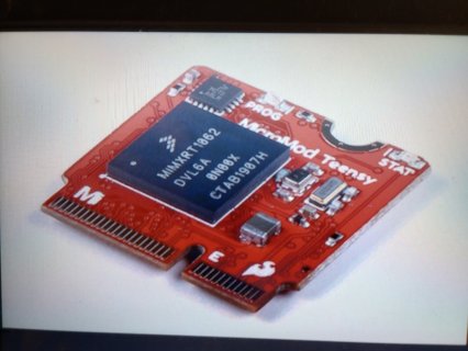
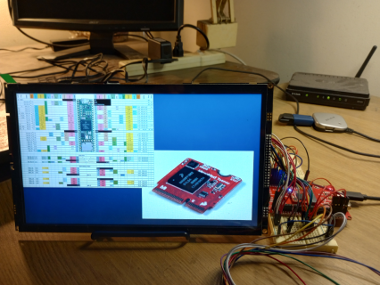
wwatson replied to the thread Buydisplay 10.1" TFT in parallel 8080 mode and Teensy FlexIO.The MicroMod is working with the ER-TFTM101-1 display. Still have to get the DMA portion working on the MicroMod. The images were produced in 8-bit mode none DMA, 100ms to display both pictures. I'm sure DMA will speed things up. By the time...
-
-
wwatson replied to the thread Buydisplay 10.1" TFT in parallel 8080 mode and Teensy FlexIO.Awesome. Now to cover any leftover SPI calls with 8080 calls and then onto the MicroMod. I am really trying keep it all in one library...
-
wwatson replied to the thread Buydisplay 10.1" TFT in parallel 8080 mode and Teensy FlexIO.Good, just finished updating the 8-bit version and the draw time was 29ms for 449280 bytes which would be close to 60ms for 800k...
-
wwatson replied to the thread Buydisplay 10.1" TFT in parallel 8080 mode and Teensy FlexIO.Here is a little background my Ra8876LiteTeeensy library. I wrote the original library. Then @KurtE and @mjs513 decided to optimize it and later @mborgerson added to the library. The the original thread can be found here...
-
wwatson replied to the thread Buydisplay 10.1" TFT in parallel 8080 mode and Teensy FlexIO.That was the issue: Teensy and RA8876 parallel 8080 mode testing (8/16) Bus speed: 40 MHZ Rotate: After Origins Drawing two pictures at 794800 bytes in 16-bit mode Draw time: 26ms This is the code now: void...
-
wwatson reacted to Rezo's post in the thread Buydisplay 10.1" TFT in parallel 8080 mode and Teensy FlexIO with Like.
That seems a bit long? 1024*600*2bpp / 40Mhz is 32.55FPS, which is roughly 30ms per full screen write. How are you getting over 200ms for two 800kb images?
-
wwatson replied to the thread Buydisplay 10.1" TFT in parallel 8080 mode and Teensy FlexIO.Not really sure. Probably should run the same test program using SPI mode on my other display to compare. Here is the sketch I am running: #include "RA8876_t3.h" #include "teensy41.c" #include "Teensy41_Cardlike.h" uint8_t dc = 13; uint8_t cs =...
-
wwatson replied to the thread Buydisplay 10.1" TFT in parallel 8080 mode and Teensy FlexIO.A quick update: I now have the T41 working with the RA8876 display in both 8-bit and 16-bit modes using the Ra8876LiteTeensy library. @Rezo was correct. The 16-bit mode is twice as fast as the 8-bit mode which makes sense when using twice as many...
-
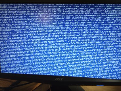
wwatson replied to the thread Buydisplay 10.1" TFT in parallel 8080 mode and Teensy FlexIO.@Rezo - I wired up the T41 for 16bit I/O and did some basic reads and writes. All failed. I hooked up my LA to monitor the first two bits of the high byte and low byte. Was reading 0xff from the status reg which was wrong. It should read 0x50...
-
wwatson replied to the thread Buydisplay 10.1" TFT in parallel 8080 mode and Teensy FlexIO.@mjs513 - That is exactly what i was looking for. You guys are the best :D Thanks Edit: That also explains why I was not seeing any signals on the "RTS-CTS" pins...
-
wwatson replied to the thread Buydisplay 10.1" TFT in parallel 8080 mode and Teensy FlexIO.@KurtE - Wow, I just finished running the blink sketch on the MMod changing the blink pin number 1 buy 1 and checking each pin with an LED to see which one was blinking. I printed out the ATP pcb image and wrote down the pin number by the...
-
wwatson replied to the thread Buydisplay 10.1" TFT in parallel 8080 mode and Teensy FlexIO.Thank you so much:D I thought I had found everything. I was looking only at the information on the ATP board. Silly ME!
-
wwatson replied to the thread Buydisplay 10.1" TFT in parallel 8080 mode and Teensy FlexIO.Sorry for The late reply, Thanks for the clarification. I will probably wire up the T4.1 for 16 bit first and then and test the MicroMod ATP. Right now I am a little frustrated trying to figure out the Teensy software pin numbering as associated...
-
wwatson replied to the thread Buydisplay 10.1" TFT in parallel 8080 mode and Teensy FlexIO.Hi Rezo, it's 1024x600. It is a good display. My vision is not good enough for anything much smaller than this display. I have not set up DMA yet. It is still using FlexIO3. Still not that familiar with using FlexIO with DMA. More to learn and...
-
wwatson posted the thread Buydisplay 10.1" TFT in parallel 8080 mode and Teensy FlexIO in General Discussion.Well I finally ordered the Buydisplay ER-TFTM101-1 with capacitive touch and had it configured for parallel communication in 8080 mode. Using parts of @Rezo's ILI984x_t41_p library, I was able to adapt my Ra8876LiteTeensy library to use the...
-
-
wwatson replied to the thread How to read/write a non filesystem USB storage drive on T4.1.@defragster - So basically you were saving the current contents of sector 10 to another buffer (sectorBufferPrior) before writing the first buffer filled with 0xaa to sector 10. Then you read the back the contents of sector 10 and did the...
-
wwatson replied to the thread How to read/write a non filesystem USB storage drive on T4.1.I have been accused of that before:) Good Luck...
-
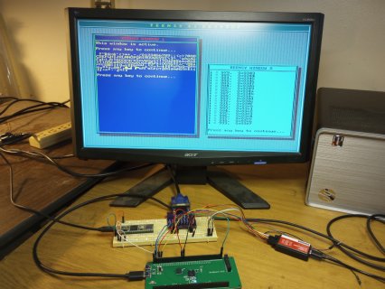
wwatson replied to the thread How to read/write a non filesystem USB storage drive on T4.1.Yes, The USB drive will have to be reformatted as stated. This is what you should see: Let's destroy any formatting on a USB thumb drive!!! Filling sector buffer with 0xaa Write 1 sector to the USB drive (512 bytes) Press any key to continue...
-
wwatson replied to the thread How to read/write a non filesystem USB storage drive on T4.1.Here is an example of doing direct sector reads and writes to a USB thumb drive. It will destroy any file system on the drive!! #include <USBHost_t36.h> // Setup USBHost_t36 and as many HUB ports as needed. USBHost myusb; USBHub hub1(myusb)...
-
Specifically regarding Arduino Giga and software, it's pretty clear Arduino has focused on developing certain features. The situation is similar with Teensy, but largely a different set of features. Depending on your perspective, it's easy to...
-
wwatson replied to the thread Teensy 4.1 or Arduino GIGA R1.I saw that as well :unsure:
-
Meanwhiles, for anyones enjoyment, here is a video of a music player demo running on LVGL v9.0.0 I think there is a lot of room left to optimize. It has two screen sized frame buffers (1.3Mb each) that LVGL writes into, and the eLCDIF reads from...
-
wwatson replied to the thread Teensy 4.0 and mp3 and FrankB's audio library.Glad you found the problem😀
-
Decided to hold off on that for now... Did lay out quick and dirty semi-shield for the Sparkfun ATP board Slight downside is that two Teensy pnis are not available (22, 28), but... The only real components to solder in are the SDIO connector and...
-
wwatson replied to the thread Teensy 4.0 and mp3 and FrankB's audio library.@WA2MZG - At one point I was having the same problem when I was adding the use of USB host drives. I started experimenting with different buffer sizes in the mp3 player code: #define MP3_SD_BUF_SIZE 2048 This is found in FrankB's...
-
-
Loading…
-
Loading…