D
DrM
- Messages
- 362
- Reaction score
- 7
Latest activity Postings About
-
-
DDrM replied to the thread S11639-01 SPI Board and Teensy 4 controller.I just updated the description on git-hub to fill in some details and explain how to use the boards - i.e., jumpers and interconnects, etc.
-
DThe Hamamatus SPI board is up and running! The design files include the sensor board and a mating carrier for a Teensy 4.0 Here is a link to the repo. https://github.com/drmcnelson/S11639-01-Linear-CCD-PCB-and-Code This is a self contained...
-
DDrM replied to the thread TCD1304 with teensy 3.2.@Qar sorry for the delayed response. If you want something that is reproducible you need a transistor follower, or better still an opamp follower, and you need an RC (resistor in series with capacitor to ground) - because (A) you are driving an...
-
DDrM replied to the thread TCD1304 with teensy 3.2.@Huyd It sounds like you are asking for help debugging. That is okay, I think. But you need to post your code and circuit. With apologies to the moderator, I think you could start a new thread, you are not really asking about the original...
-
DDrM replied to the thread T4 interrupt latency and etc.P/S I plan to put this up on my git-hub, just havent gotten around to it. Need to find some time to generate the readme. Again the idea is "time your arduino", I tried to stay with the API as far as possible and not go to bid fiddlin'. The...
-
DDrM replied to the thread T4 interrupt latency and etc.@kd5rxt-mark I attached a complete code a few messages back. But here is the current code, which now includes the API described two messages back. This is the api I plan to use in my own work. Please see the attachment. Start the sketch...
-
DDrM replied to the thread T4 interrupt latency and etc.@PaulStoffregen Thanks for the book tip, it looks good, I ordered it. I see it has some information on ice. So that is really helpful.
-
DDrM replied to the thread T4 interrupt latency and etc.@PaulStoffregen Hi Paul, two things perhaps of interest. First, here is my API for the direct attach. I think it would be nice to have something like this available in the general API. If so, the directDetach could simplified. volatile...
-
DDrM replied to the thread T4 interrupt latency and etc.@PaulStoffregen Yes, it was the attachInterrupt() that I was concerned about. In interrupt.c, at line 89 it invokes NVIC_ENABLE_IRQ(IRQ_GPIO6789); Does that mean that interrupts become enabled again while I am still in my ISR? I thought...
-
DDrM replied to the thread T4 interrupt latency and etc.@PaulStoffregen Hi Paul, it works! Thank you. I have one question though, how do we restore the generic interrupt handler? Trying to load it with attachInterruptVector() gives an undefined reference. Another strategy, actually the one I...
-
DDrM replied to the thread T4 interrupt latency and etc.Okay, with that ado, and pending comments, I'll give it a try, on labrat hardware, and see what happens.
-
DDrM replied to the thread T4 interrupt latency and etc.@PaulStoffregen P/S - further thought on the previous. I think i need to restore the previous interrupt handler when I am done, so that external triggers will be recognized again. That would mean doing something like this before i leave the...
-
DDrM replied to the thread T4 interrupt latency and etc.@PaulStoffregen Hi Paul So looking at interrupt.c, it seems like irq_anyport() is the generic handler, and the source of the interrupt is cleared in the line gpio[ISR_INDEX] = status (the usual "write the bit to clear the bit" kind of thing)...
-
DDrM replied to the thread Timings, Latencies and all that - redux.@jmarsh, if you are interested, see Pauls' reply here https://forum.pjrc.com/index.php?threads/t4-interrupt-latency-and-etc.74688/post-340883 Paul confirms that there is a "generic" handler that calls the user supplier function, and provided...
-
DDrM replied to the thread T4 interrupt latency and etc.@PaulStoffregen Thank you Paul, that is super helpful. I really appreciate it, I think you have saved me a lot of time. Fantastic.
-
DDrM replied to the thread Timings, Latencies and all that - redux.P/S thinking about this a little further, the jitter is really limiting, at 25% it is just too large and easily a show stopper for what would otherwise be some great applications for a 600MHz ARM platform. Perhaps there is another API that I am...
-
DAttached is (A) a sketch that measures timings for adc reads, digital read, write, toggle, shortest pulse, and interrupt latency measured as time from edge assertion to the user supplied ISR, and (B) a header file generated by the sketch that...
-
-
DDrM replied to the thread T4 interrupt latency and etc.@PaulStoffregen Fair point, and I did intend but forgot to include the attachInterrupt(). I was in a hurry over unrelated matters. Anyway, your code example demonstrates everything there is to the question, that is indeed how I am setting up...
-
DDrM replied to the thread T4 interrupt latency and etc.10 nsecs is a decent time to first instruction in an ISR, a few cycles for register saves after that or a single instruction context swap in some processors. Anyway it turns out the ARM7 has 37 registers. So that is the 72 cycles for an...
-
DDrM replied to the thread T4 interrupt latency and etc.@MarkT, 72 instruction cycles? That is not consistent with experience on other platforms.
-
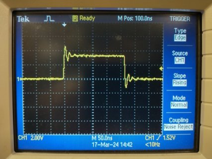
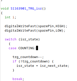
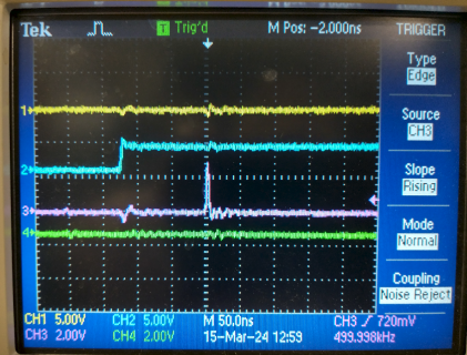
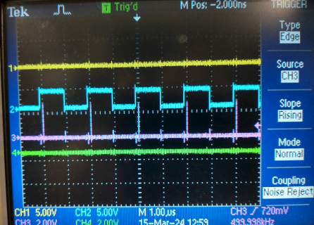
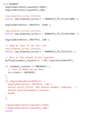
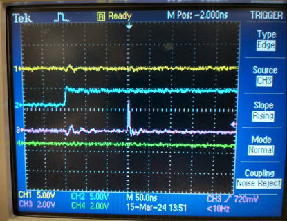
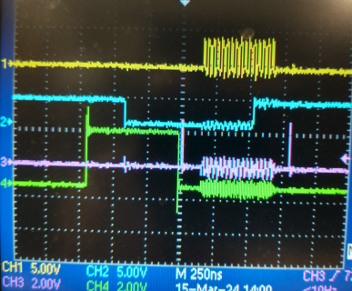
DI am trying to implement a state machine in an isr, and find some interesting timing problems. Here is a synopsis of how it works, but you can skip this for the question. The external parts are an S11639-01 (CCD sensor) interfaced and a...
-
-
DDrM replied to the thread [posted] USB DAQ with the Teensy.@Paul Thank you, very interesting.
-
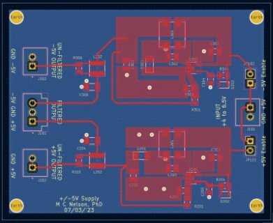
DDrM replied to the thread [no Teensy?] +/-5V power from USB.This +/-5V supply is the enabling piece for a lot of the circuits that I build specifically to use with the Teensy. For example, I am about to spin a new instrumentation interface and a waveform generator, both 16 bits 1MHz to use with the...
-
DDrM replied to the thread Future Teensy features & pinout.I dunno, peripheral connectivity can be useful, it might have a cost in power and heat. So, as always, you have to think about what it is for, and what other platform might be appropriate, And, as a corollary, the broader the range of use...
-
DDrM replied to the thread Software reboot for the T4.@PaulStoffregen @jmarsh Thank you
-
DIs there a way to reboot the T4 from within a sketch? For example, here is a restart() function for the T3. How would we code a restart() for the T4? #define RESTART_ADDR 0xE000ED0C #define WRITE_RESTART(val) ((*(volatile uint32_t...
-
DDrM replied to the thread ADC tests for TCD1304DG.One thing I should correct, or be more clear about: With the master clock at 2MHz, you read the device at 500KS/s, or about 8 msecs per frame. For the T4 with its 480 Mb/s USB, the readout from the sensor should be what sets your maximum frame...
-
DDrM replied to the thread ADC tests for TCD1304DG.In preface, using the TCD1304 (or any CCD), and obtaining results that are useable, at least reproducible and proportional to your light input, is not trivial. Here are some of the issues: (A) light corruption vs "keep clean" and...
-
DDrM replied to the thread [no Teensy?] +/-5V power from USB.@Angelo Again, that is what it does. It is a working design that has been used for years. It was developed in consultation with another very expert instrumentation physicist and the engineers at Analog, and we do understand impedance, one of...
-
DDrM replied to the thread [no Teensy?] +/-5V power from USB.@Angelo Thinking about it some more, in the areas that are not directly connected to the IC, maybe I could squeeze it a bit. When you look at it carefully though, I don't think it is going to improve anything very much. But, maybe I'll try...
-
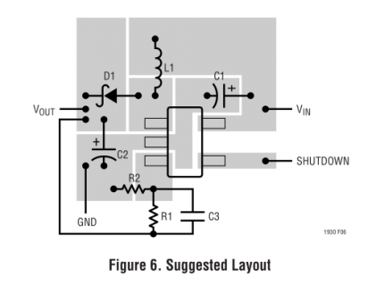
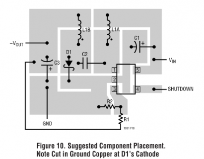
DDrM replied to the thread [no Teensy?] +/-5V power from USB.@Angelo Here are the layouts from the datasheet (and another of the board). You'll notice they look a lot like the board. In fact, originally, I traced one of them. The other has one mod for the septic. And, the design was reviewed by two...
-
-
DDrM replied to the thread [no Teensy?] +/-5V power from USB.@strud Looks nice, pretty good current noise, slew, CMRR, PSRR. Is the max diff input +/-1V, enough for your application? Re the designs. I am posting a series of designs and firmware to my github page. Some of these are designs that I...
-
DDrM replied to the thread [no Teensy?] +/-5V power from USB.I want to mention two more details about the dual supply design shown in the original post. 1) The LT1930 is used in the SEPIC configuration. The board provides +5V and -5V, even when the input is well below USB, to as low as 2.6V. And, the...
-
DDrM replied to the thread [no Teensy?] +/-5V power from USB.@strud The LM27762 is a little different. In that device, the positive supply is generated from an LDO. For a +4V output (from USB in) you are probably okay (the LDO will drop out for voltages near USB). Even for a 4V design, I think you...
-
-
Loading…
-
Loading…