XRAD
Well-known member
- Joined
- Last seen
- Messages
- 67
- Reaction score
- 1
Latest activity Postings About
-
-
 XRAD replied to the thread Teensy 4.0, 'disabling' an analogRead pin.So I switched the cap over to the sensor input side of the voltage divider(Thx MarkT), and re-adjusted the slope calculation for the new voltage drop, and with a little tweaking of slope, I am now getting steady and fairly accurate readings. THX...
 -
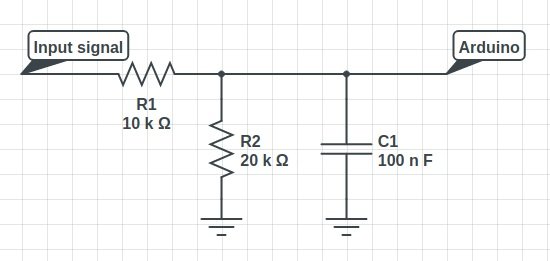
XRAD replied to the thread Teensy 4.0, 'disabling' an analogRead pin.yep, the regulated 3.3v, not 5v. I will get rid of the 4k7. My voltage divider circuit is similar to above, but without the diodes. I thought the cap (mine is a 10nf) went from the divided resistors to ground? not the input signal to ground...
-
-
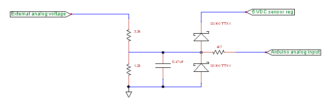
XRAD replied to the thread Teensy 4.0, 'disabling' an analogRead pin.thx for replies! I read about the diode setup. I just don't have any on hand and was wondering about other options via code. I will give the diodes a try. Something like this? THX!
-
-
-
Loading…
-
Loading…