R
Rezo
- Messages
- 550
- Reaction score
- 58
Latest activity Postings About
-
-
RNote: that is simply a print to pdf of one of the pages in the excel document: https://github.com/KurtE/TeensyDocuments/blob/master/Teensy4x%20Pins.xlsx Note: @mjs513 did a modified version of this that I think is in @defragster github project...
-
RMy main question would be, what do you even need the Teensy/Arduino pin numbers for when writing code for modules like CSI and FlexIO? You can use IOMUXC_SW_MUX_CTL_PAD_GPIO_x and IOMUXC_SW_PAD_CTL_PAD_GPIO_x to initialize them (which works...
-
RRezo replied to the thread Call to arms | Teensy + SDRAM = true.@KurtE can we get an original excel copy of this so that we can edit it? https://github.com/KurtE/TeensyDocuments/blob/master/Teensy4%20MicroMod%20Pins.pdf
-
RA couple of questions and things I am playing with... With the 4.5 and SD adapter: guessing you used SDIO pins? (Same ones as defined for Micromod?) of if SPI which IO pins? CSI pins - I am in the process of integrating in some CSI support...
-
R@KurtE and I have been at it again. This time creating a library that supports a number Arducam/Arduino camera modules: Model FrameSizes Pixel Formats Omnivision OV2640 FRAMESIZE_VGA //640x480 FRAMESIZE_QQVGA, // 160x120...
-
RSo I decided to make a facelift, adding SDCARD and USB-PD which supports the PD protocol up to 12V. There are pads to solder if you just want to use the second port as a pass through with 5V. Meaning, it will deliver the same 5V coming into the...
-
RWow you been busy!!! Nice job
-
ROne question did you bring out the csi pins?
-
RI did not bring out any special ports. All that was done was SDCARD and USB-PD. But ofc we can keep going and make a gen5 that has more stuff. But it needs coordinating, Rezo and KurtE together could make a full pin mapping, that would be ideal...
-
RRezo replied to the thread Call to arms | Teensy + SDRAM = true.It's hard to troubleshoot these things online, but can yo do a simple test with a logic analyzer? similar to what I did here? We need to verify that the data is being sent out in the correct order. The DMA is set up specifically to accept a 16...
-
RRezo replied to the thread Call to arms | Teensy + SDRAM = true.@wwatson the code looks good from a brief overview. What length wires are you using between the MCU and the display boards? WIth 10cm wires I could not get past 20Mhz when testing With an LCD and Micromod mounted to the same pcb with 2cm traces...
-
RRezo replied to the thread Call to arms | Teensy + SDRAM = true.@wwatson Are you trying 16 bit FlexIO on the dev board? If you have it working on a 4.1, then the config should be almost identical, but you need to make sure of the following changes: Set the relevant pins to output mode, and set the MUX to...
-
RRezo replied to the thread Problemes with DIY Teensy 4.1.You have to order the boot loader from PJRC. It has custom code on it that allows the 1062 to work with Arduino/Teensyduino. A fresh boot loader should work on an unpaired 1062. @PaulStoffregen can confirm
-
RRezo replied to the thread Problemes with DIY Teensy 4.1.Flash memory is not fused, so it can be replaced. But the RT1062 and the MKL02 are fused together the first time they both power up.
-
RRezo replied to the thread Problemes with DIY Teensy 4.1.Everything is mentioned on the bootloader page - https://www.pjrc.com/store/ic_mkl02_t4.html If you got as far as creating your own Teensy 4.1, you should have come across this at some point
-
RHere is the SDRAM board and ER-TFTM101-1 TFT working in 8080 8-bit mode. It's a start:) Waiting on some info to try out 16-bit 8080 mode...
-
RRezo replied to the thread Flashing 4.1 code on a board with a 4.0 bootloader chip.My morning just begun :) Update us how it goes
-
RRezo reacted to wwatson's post in the thread Flashing 4.1 code on a board with a 4.0 bootloader chip with
 Like.
Thanks @Rezo - Will set it up in the AM. Bedtime...
Like.
Thanks @Rezo - Will set it up in the AM. Bedtime... -
RRezo replied to the thread Flashing 4.1 code on a board with a 4.0 bootloader chip.@wwatson Set the pin to FlexIO IOMUXC_SW_MUX_CTL_PAD_GPIO_B0_00 = 4; Set pin as output, high strength drive: IOMUXC_SW_PAD_CTL_PAD_GPIO_B0_00 = 0xFF; Do this for all 16 pins. You can still use FlexIO library, you just don’t need to call the...
-
RRezo replied to the thread Flashing 4.1 code on a board with a 4.0 bootloader chip.@wwatson I set it through the IOMUXC just like jmarsh did. I have a 24bit 8080 FlexIO library I put together for an RM68120 display that died half way though development - I’ll dig it up and share the init code
-
RRezo replied to the thread Call to arms | Teensy + SDRAM = true.If those pins are not responding but adjacent pins are, then there is a hardware issue with the board, bad BGA soldering from the production run. @Dogbone06 FYI
-
R@jmarsh - Tested the elcdif sketches. Impressive:D Did not realize the mandelbrot sketch was animated. Now to hook up the 10.1" LCD and test... EDIT: By the way the T41 on the breadboard is the first T41 I got from PJRC. It has the white...
-
RRezo replied to the thread Teensy 4.1 on macOS 10.13.You might have bought a counterfeit teensy. Can you share the link to the product on Aliexpress?
-
RThanks for the info and link above. I now have it working with external sdram. It seems to work ok up to 270MHz with a 1280x720 frame buffer. Excuse my shakey picture:) I still am not using double buffering like in your original sketch but it...
-
RFirst simple experiment on SDRAM board works. Adapted my 4-bit VGA library based on @jmarsh's driver to the dev board. Just had to change two pin defines for FlexIo2 for HSYNC and VSYNC which is used in several places in the FlexIO begin method...
-
RJust received the sdram development board today:D I ran through all of the test programs that I know about without a problem. I need to make sure I have all of the pinout info for this board. It is a version 4 board. I thought I would start out...
-
RRezo reacted to ledmasters's post in the thread [posted] My first Teensy 4.0 project and radio link to Feather MO + printer with Like.
I have had fun developing a Chronograph for measuring bullet speed with a Teensy 4.0 with 3.2in tft and RFM69 radio link to a Feather M0 with the 433mhz onboard radio. Also added a Nano printer to the wireless display for a hardcopy at the...
-
RRezo reacted to wwatson's post in the thread Buydisplay 10.1" TFT in parallel 8080 mode and Teensy FlexIO with Like.
Thanks, I'll take a look at it. So far it has been my lack of knowledge of FlexIO and DMA that has slowed me down but I'm starting to understand it more...
-
RRezo replied to the thread T4 ADC high speed sampling - how to?.@mborgerson thanks for taking the time and putting this together. I will have a play with it in the coming days!
-
RRezo replied to the thread Buydisplay 10.1" TFT in parallel 8080 mode and Teensy FlexIO.I had issues just as you have above with the DMA write, but I can't recall what it was. Worth reading though my comments in this FlexIO thread - my memory is just not good enough to recall what the root cause was. But I have a feeling it's the...
-
RRezo replied to the thread Buydisplay 10.1" TFT in parallel 8080 mode and Teensy FlexIO.Can you comment out gpioRead(); ? I think it's redundant.
-
RRezo replied to the thread Buydisplay 10.1" TFT in parallel 8080 mode and Teensy FlexIO.what clock source are you using? And prescalers? When I was playing with FlexIO initially I found that the clock speed had to be half of the clock source speed. Eg if the clock source is 480Mhz, the maximum FlexIO clock speed can be 240Mhz. When...
-
RRezo reacted to Northstrix's post in the thread [queued] DIY Hardware Data Vault With Teensy 4.1 (Midbar (Teensy 4.1) V3.0) with Like.
Midbar (Teensy 4.1 Version) V3.1 is released. This version of Midbar can encrypt data that can be decrypted in the desktop app and vice versa. The new feature is available in the "Other Options" -> "Custom Key Encryption" -> "AES-256 CBC" tab...
-
RRezo replied to the thread T4 ADC high speed sampling - how to?.Thank you, I appreciate the time spent on helping out! 1. The signal will be attuned, but the target is 5-15kW amplifiers, so peak to peak voltages of up to 400-500 volts. Plan is to use a voltage divider to get the levels down to around 3vpp...
-
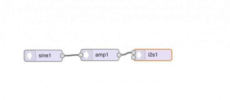
RRezo replied to the thread Simple audio sine signal generator.Thanks @PaulS
-
RYes, your design will do. Set the sine module output to 1.0 and set the attenuation or amplification at the amp module. Paul
-
RI need to build a test rig for another Teensy based project that can generate an audio sine wave from 0-20Khz, but I need to be able to make the signal clip as well. I have a a T4.x and a Rev D audio shield here at home - would this +a simple...
-
-
RRezo replied to the thread High temperature shutdown T4.1.You can alter the alert/panic temps in the core files: https://github.com/PaulStoffregen/cores/blob/master/teensy4/tempmon.c#L10 Change this at your own risk. I have set my panic to over 100c for a product that sits in direct sunlight (and is...
-
RRezo replied to the thread Call to arms | Teensy + SDRAM = true.To be honest im not sure either. Why would you need to know supply voltage if it won't work with anything much less than 3.3v? Also if it's battery powered there will be a DC-DC converter providing a stable 3.3v regardless of cell voltage...
-
RRezo replied to the thread Call to arms | Teensy + SDRAM = true.We copied the Micromod pin pad labels, that's why it says BATT_IN - it's a Micromod label. It is wired to 3.3v on the ATP board and any other MM carrier board with a voltage divider. But it's just a GPIO, so can be used for anything else on the...
-
RFinally got around to sitting down and mapping out all the exposed pins properly and found something odd - there's a pin labelled BATT_VIN/22/A8. My first thought: "how can this pin be both BATT_VIN and an I/O pin?" The answer is it can't/isn't...
-
RRezo replied to the thread T4 ADC high speed sampling - how to?.@mborgerson anything you can suggest? The comparator rout seems like a very good trigger option so start/stop ADC samples. Perhaps use two buffers, so while one is being filled via DMA the other can be read and calculated. Just need some...
-
RRezo reacted to wwatson's post in the thread Buydisplay 10.1" TFT in parallel 8080 mode and Teensy FlexIO with Like.
Awesome. Now to cover any leftover SPI calls with 8080 calls and then onto the MicroMod. I am really trying keep it all in one library...
-
RRezo replied to the thread Buydisplay 10.1" TFT in parallel 8080 mode and Teensy FlexIO.For a full 1024*600 @ 2bpp frame on an 8 bit bus with a 40Mhz baud rate you should get up to 16fps. No super fast, but for such a high resolution and narrow bus, that's as good as it will get!
-
RRezo reacted to wwatson's post in the thread Buydisplay 10.1" TFT in parallel 8080 mode and Teensy FlexIO with Like.
Good, just finished updating the 8-bit version and the draw time was 29ms for 449280 bytes which would be close to 60ms for 800k...
-
RRezo replied to the thread Buydisplay 10.1" TFT in parallel 8080 mode and Teensy FlexIO.Thats looks much better!
-
RRezo reacted to wwatson's post in the thread Buydisplay 10.1" TFT in parallel 8080 mode and Teensy FlexIO with Like.
That was the issue: Teensy and RA8876 parallel 8080 mode testing (8/16) Bus speed: 40 MHZ Rotate: After Origins Drawing two pictures at 794800 bytes in 16-bit mode Draw time: 26ms This is the code now: void...
-
RRezo replied to the thread Buydisplay 10.1" TFT in parallel 8080 mode and Teensy FlexIO.Biggest issue I see is each time you write a pixel you are calling flexio config and asserting/de asserting CS/DC - thats wasted time. In your function putPicture_16bppData16 you already have a pointer to data. So you just write the data to the...
-
RRezo replied to the thread Buydisplay 10.1" TFT in parallel 8080 mode and Teensy FlexIO.That seems a bit long? 1024*600*2bpp / 40Mhz is 32.55FPS, which is roughly 30ms per full screen write. How are you getting over 200ms for two 800kb images?
-
-
Loading…
-
Loading…