M
MarkT
Well-known member
- Joined
- Last seen
- Messages
- 2,250
- Reaction score
- 40
Latest activity Postings About
-
-
MMarkT replied to the thread U4 Chip gets extremely hot when 4.1 is connected to power..Connecting a motor direct to pin 8 of the Teensy? That doesn't sound safe, back EMF, burn out the pin through overcurrent, ESD through handling the motor - several ways this could be bad news.
-
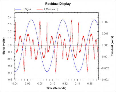
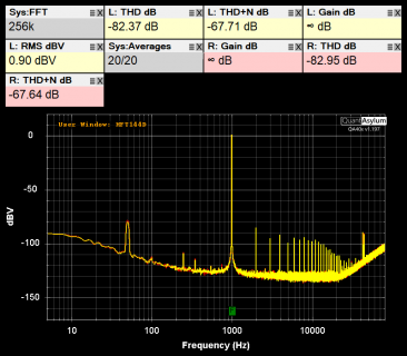
MMarkT replied to the thread Measured performance of line in and line out of SGTL5000.Yes, its an unmodified Audio adapter D that I've had for a while but only just soldered headers too and started using. Since the QA403 has high input impedance the caps distortion should be relatively low. I hope they are C0G/NP0 type...
-
-
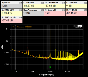
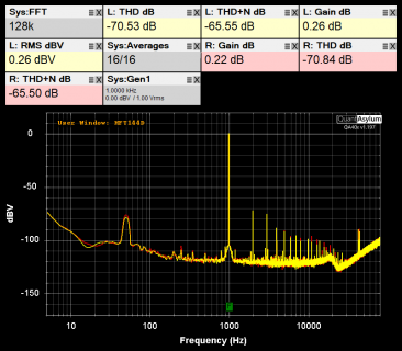
MMarkT replied to the thread Measured performance of line in and line out of SGTL5000.Yes I think 80kHz for the measurement bandwidth - which may be a little unfair. Well you could measure it directly by sending to USB and capturing the raw data without using any DAC for a definitive answer - the SGTL DAC is clearly dominating...
-
MMarkT replied to the thread Measured performance of line in and line out of SGTL5000.AudioSynthWaveformSineHires seems to make a very small difference of 0.5dB or so:
-
-
MMarkT replied to the thread Measured performance of line in and line out of SGTL5000.Good point. Will retry later.
-
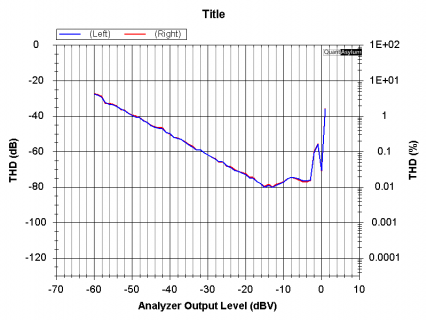
MI took the Waveforms Audio example, set the frequencies to 1000Hz, wave type to sine, and maxed the levels with sgtl5000_1.lineInLevel(0); sgtl5000_1.lineOutLevel(13); And looked at the line outputs with my QA403 audio analyzer: Which...
-
-
MMarkT replied to the thread Teensy 4.1 SPI Slave - No correct data reception.It probably sent part of the chip into CMOS latchup...
-
MMarkT replied to the thread How to change sample rate by use "sgtl5000".Yes, you are missing SYS_FS and MCLK_FREQ, also in CHIP_CLK_CTRL which sets the clock, this in combination with the RATE_MODE determines the sample rate, see datasheet table 18. I think you'll need to reduce the MCLK frequency sent to the chip...
-
MMarkT replied to the thread External Power Supply Issues.Well the schematic does not show the power supply arrangements or decoupling for one thing. Where does the +/-15V come from for instance? I do note the TL072 trying to drive 470nF through 16 ohms - likely to oscillate, opamps can't drive heavy...
-
MMarkT replied to the thread Teensy 4.1 SPI Slave - No correct data reception.The T4 is absolutely _not_ 5V tolerant, 3.3V is the limit for all pins - this is clearly stated in the data for the device. You require level converters to talk to a 5V chip (if you haven't fried the T4 already).
-
MMarkT replied to the thread Win11 doesnt recognize Teensy.Recommend testing every USB cable you get whether it has data and if not marking it conspicuously...
-
MMarkT replied to the thread Arcade Buttons with WS2812.Why would you need to use non-blocking WS2812 update? They update fast enough, you only have human input to respond to so interrupts won't be needed.
-
MMarkT replied to the thread SGTL5000 Microphone Input - How long can the conductors be between mic and board?.Or this: https://www.canford.co.uk/CANFORD-HSS-HELICAL-DOUBLE-SCREENED-SINGLE-CABLE
-
MMarkT replied to the thread Magnetic Encoder not working with teensy 4.1 but is with teensy 3.2.The T4 can switch extremely fast, 10ns or something like that, even digitalWrite is very fast (though not quite that fast!). There is a delayNanoseconds() call which can be useful on the T4.
-
MMarkT replied to the thread SGTL5000 Microphone Input - How long can the conductors be between mic and board?.Shielded for audio usually. Twisted pair is only immune to capacitive interference if balanced impedance.
-
MMarkT replied to the thread Servos Misbehaving.please describe in more detail how you are powering them than Part number, current rating, that sort of detail is essential. A diagram is helpful so we are on the same page.
-
MMarkT replied to the thread [solved] Teensy 3.2 SPI speed decreasing over time.uint16_t r = (sin(t + 60.0 * 0.0) * max + max); uint16_t g = (sin(t + 60.0 * 1.0) * max + max); uint16_t b = (sin(t + 60.0 * 2.0) * max + max); Suggests an assumption that sin takes degrees rather than radians, so there are...
-
MMarkT replied to the thread Servos Misbehaving.Servos take a lot of current, please describe in more detail how you are powering them, the current ratings of the parts etc. Also which servos are you using?
-
MMarkT replied to the thread Why is controlling filter frequency with envelope causing distortion?.See this thread: https://forum.pjrc.com/index.php?threads/envelope-detector-and-vca-with-teensys-audio-library.29579/ abs means absolute value as in envelope detection.
-
MMarkT replied to the thread "String" range issue.The code has 536's all over the place, it should be #define'd or a const value in one place...
-
MMarkT replied to the thread "String" range issue.44100/(2*536) = 41.138
-
MMarkT replied to the thread i2s bluetooth transmitter.Converting I2S to BLE isn't a trivial thing, you want that supported in the chip directly...
-
MMarkT replied to the thread Understanding how I killed Teensy 4.0 Serial1 with simple circuit.Hot-plugging requires a connector where ground & power connects before data, as in a USB plug. Otherwise in your case you can get a situation where only the 12V and a data line are connected, putting 12V through the Teensy. Alternatively add...
-
MMarkT replied to the thread i2s bluetooth transmitter.Did you read the details on that page where it explains how it connects/pairs?
-
MMarkT replied to the thread "String" range issue.No, just an arbitrary limit in the source code... Note the TODO comment acknowledging this isn't ideal! Someone got time to do a PR on this maybe?
-
MMarkT replied to the thread Using AudioMemory - AudioMemory changes analog readings from a microphone.The FFT relies on gathering 8 consecutive audio blocks and then gets to work. Without 8 distinct blocks it will have wrap-around and mess up audio block allocation for the whole audio chain I believe.
-
MMarkT replied to the thread "String" range issue.The length of the delay line is limited to 536 entries: int16_t buffer[536]; // TODO: dynamically use audio memory blocks Which corresponds to a round-trip delay of 24.3ms, which is 41.13Hz
-
MMarkT replied to the thread Using AudioMemory - AudioMemory changes analog readings from a microphone.You need a minimum of 8 128-sample audio blocks to work with FFT of size 1024 as 8*128 = 1024.
-
MMarkT replied to the thread short circuit somewhere killing all my teensies?.No, a diode is used for DC, a snubber circuit for AC. Diodes are always fast enough to conduct (its turn-off that can be slow).
-
MMarkT replied to the thread Could the Teensy 4.1 be affected by interference emitted from the RF module?.It is interference, completely expected unless you properly shield the components - if you look at every radio-transmitter you'll see the design involves various compartments all individually shielded (Faraday cage). You need to do the same, put...
-
MMarkT replied to the thread Could the Teensy 4.1 be affected by interference emitted from the RF module?.That RFD868 module seems to output upto "30dB", which I take to mean +30dBm (i.e. one watt). Yes that's going to kill nearby circuitry easily if not shielded properly. Typical dipole antenna voltages for 1W might be upto 50Vrms at the tips, so...
-
MHi all. We built a school playground using Teensy 4. Instagram post Interface is a Teensy 4 with 3x mpr121 and rs485. We have another Teensy 4 to process the commands, send midi data, play music (Teensy Audio Shield), control relays and LEDs...
-
MMarkT replied to the thread Designing an Inverse Notch Filter?.A biquad with setBandPass is clearly the way to go... Very high Q may cause stability issues though, but you should be able to get higher than 5...
-
MMarkT replied to the thread 6 DC motors with 3 drv8833 Motor Drivers on a Teensy 4.1?.Start with one. The DRV8833 datasheets how to use it in fast-decay and slow-decay modes. There are encoder libraries for standard quadrature AB and ABZ encoders.
-
MMarkT replied to the thread Audio board (REV D)..That's a coupling capacitor. The 2.22uF below it is the decoupling cap. The connector is DC-linked to MICBIAS output, which is why an external coupling capacitor needs to be used if the source doesn't handle a DC-offset.
-
MMarkT replied to the thread Audio board (REV D)..You'll need a DC-blocking cap as the microphone pads are designed for an electret capsule. I'm not sure what you mean by a GBF, gain before feedback is a measurement.
-
MMarkT replied to the thread RTC Crystal Part Number.Plain crystals are never temperature compensated, they are just a sliver of quartz, only crystal oscillators, aka TCXO, have compensation. The microcontroller datasheet will probably have the specifications for the RTC XTAL.
-
MMarkT replied to the thread Teensy 4.0 / 74HC595N shift register compatibility issues?.60ns is 72 instructions on the T4 (assuming dual-issue is fully utilized)!!
-
MMarkT replied to the thread Is it possible to change the frequency of the internal DCDC converter?.Glad its solved!
-
MMarkT replied to the thread Teensy 4.0 / 74HC595N shift register compatibility issues?.74HCxx family at 3.3V can allegedly clock upto about 40 or 50MHz, though I would play safe and aim for 30MHz max. 74LVC595 would be considerable faster as its designed for 3.3V.
-
MMarkT replied to the thread Is it possible to change the frequency of the internal DCDC converter?.Putting the Teensy Micromod in a Faraday cage is worth considering.
-
MMarkT replied to the thread LED PWM without resistor.No, use a resistor, or you'll fry the LED or the Teensy. The absolute maximum ratings are just that. Exceed them and degradation and failure can happen. Why not consider a neopixel which takes one control signal and does the PWM for you?
-
MMarkT replied to the thread Including a library after booting.#include's happen at compile time. You are asking for something like dynamically linked runtime libraries, loaded from a filesystem at runtime (SDcard?), or something like code overlays. Do you actually have a problem with running out of code...
-
MMarkT replied to the thread T4 interrupt latency and etc.Remember there's also the time to de-glitch the input and process the vectored interrupt, not every part of the chip is clocked at the full 600MHz either. Anyway 72 cycles is only 120ns at 600MHz, which is very fast for an ISR response. Beyond...
-
MMarkT replied to the thread T4 interrupt latency and etc.No, it has to save all the registers it uses to stack which is many cycles. When the interrupt occurs it has no knowledge of which registers are live or not so it has to save all the ones it will clobber, not just the callee-save set like a...
-
MMarkT replied to the thread Low-latency two-level partitioned convolution for the T4.Its been a while since I used this, it might be a lack of memory (only the setSampleCount() function currently reports back a success value, the setFIRCoefficients() call blindly ignores if setSampleCount() fails - that needs fixing really, both...
-
MMarkT replied to the thread 1830 Hz noise when there is no input.Maybe it is fussy about the ESR of the decoupling capacitor?
-
MMarkT replied to the thread I2S Speed (768kHz?).Left justified is a variant of I2S with a 1 bit timing shift of the data. It is easier for some chips to handle. Audio ADCs and DACs are all at least stereo because why wouldn't they be...
-
MMarkT replied to the thread sampling arbitrary analog input at fixed samplerate.Best done with DMA, although more complex to setup - interrupts are subject to timing variation from other interrupts, critical sections etc. The Audio library analog input class might be a source of inspiration.
-
MMarkT replied to the thread I2S Speed (768kHz?).4 channels? They would run in parallel, so BCLK for 32bit 768k is 64 x 768k = 49.152MHz, which has a period of ~20ns. There might be a ratio between MCLK and BCLK, but its not to do with channels, hopefully the device doesn't need MCLK anyway?
-
-
Loading…
-
Loading…