T
Thundercat
Well-known member
- Joined
- Last seen
- Messages
- 137
- Reaction score
- 1
Latest activity Postings About
-
-
TThundercat replied to the thread Issues Connecting Teensy 4.0 to Newer Macs with USB-C.Thank you Paul. I'm looking into it with the cable manufacturer. I had custom cables made; perhaps they didn't follow spec. I'll post back what I find out from them. Thanks again!
-
TThundercat reacted to PaulStoffregen's post in the thread Issues Connecting Teensy 4.0 to Newer Macs with USB-C with
 Like.
A properly made USB C to USB Micro B (or any of the non-C device connectors) cable should have those 5.1K resistors built in.
Like.
A properly made USB C to USB Micro B (or any of the non-C device connectors) cable should have those 5.1K resistors built in. -
TThundercat replied to the thread Issues Connecting Teensy 4.0 to Newer Macs with USB-C.Hi blackketter, that is super helpful. It sounds like an ongoing issue for these kinds of units. Can this be solved with a special cable with the 5.1k resistors on CC lines on both sides? Or is it a lot more involved? I am currently using a USB...
-
TThundercat reacted to blackketter's post in the thread Issues Connecting Teensy 4.0 to Newer Macs with USB-C with Like.
Check out: https://hackaday.com/2023/01/04/all-about-usb-c-resistors-and-emarkers/ You might need a USB-C adapter that has the requisite resistors.
-
TThundercat posted the thread Issues Connecting Teensy 4.0 to Newer Macs with USB-C in Technical Support & Questions.Hi, for some time now I've been using internal USB-micro-B to USB-C adapters with my units that I sell with Teensy 4.0s. That way, externally on the units, users have a nice USB-C connector. It's been working fine. Lately, however, I've noticed...
-
TThundercat replied to the thread Lockable Teensy Flash Question.Thank you!
-
TThe 3 programs you get when you click the 3 buttons in the Teensy 4 Security tool (which only exists in Arduino IDE 1.8.19, Tools > Teensy 4 Security menu)
-
TThundercat replied to the thread Lockable Teensy Flash Question.Thank you Paul. Sorry to be obtuse, but what 3 programs? You mean Arduino 1.8x, Ardxuino 2.x, and Teensyduino? I'm aware of the need to keep the key.pem safe, and have backups of it (I do), but I don't understand your middle paragraph...are you...
-
TThundercat replied to the thread Lockable Teensy Flash Question.Thank you so much defragster! I really appreciate it. Do you ever sleep? :)
-
TThe only need for IDE 1.8.19 is the locking steps. The IDE 2.x limitation is presenting UI to run the code for the locking steps. Once locked both IDE 1.x and 2.x will generate the .eHex required to upload to a locked Teensy.
-
THi, I am using locked Teensy 4.0's for my business ventures. I've run into an issue where the Teensyduino IDE crashes a lot, as it's based on the 1.8x Arduino Code, and I get java heap errors (there's another thread about this, but not work...
-
TThundercat replied to the thread Arduino/Teensy IDE Crashes Constantly - Java heap errors.I know I didn't respond to this in a long time; apologies. I found the fix did not work. When I try to use the fix Paul gave, the program quits shortly after launch. So I went back to the original. I'm still having the out of memory errors. I...
-
TThundercat replied to the thread Potentiometers not giving full range: 4 - 1008 only.Just an update, I've redesigned the PCB to conform to Paul's suggestions, with a slight twist. I've put the pots on their own dedicated GND pin on the Teensy, as well as their own dedicated 3.3V pin. But instead of using traces, I've put a small...
-
TThundercat replied to the thread Cannot upload sketch to teensy 4.0.Just an update. I examined the board carefully, and no visible damage anywhere. I did what I never do - flooded the whole thing with 99% isopropyl alcohol and brushed it vigorously with a brush - to remove all traces of flux from the board. I use...
-
TThundercat replied to the thread Cannot upload sketch to teensy 4.0.Thank you Paul. I will examine the board. However, I had already successfully flashed it several times. Seems more than odd that stray solder would become a problem 2-3 weeks later… In any case, I appreciate your expertise. If I find anything...
-
TThundercat replied to the thread Cannot upload sketch to teensy 4.0.Does anyone have any thoughts? This is a brand new Teensy. They're usually pretty bulletproof. I can add that this is a lockable Teensy 4.0, and it's locked, and I've been using lockable Teensys like this for a long time. It simply fails to...
-
THi, I've been using the platform for a few years, and have used many many dozen Teensy 4.0s. I recently flashed a new Teensy 4.0, no issue, and tonight I tried to update it, but the Teensy loader program fails. It just says to press the button...
-
TThundercat replied to the thread Potentiometers not giving full range: 4 - 1008 only.Hi, question - from other posts it seems AGND is identical on the Teensy 4.1 now. It would be easier for me to route the analog grounds to a different ground pin. Just to confirm, the AGND is the same as any of the other GND pins now on Teenys...
-
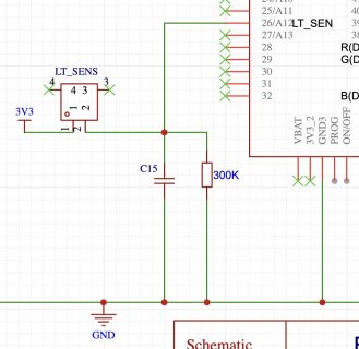
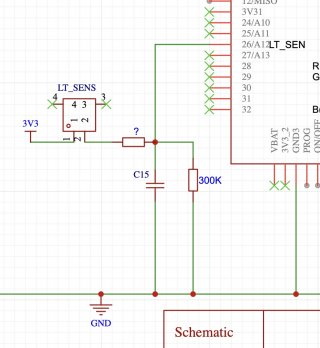
TThundercat replied to the thread Potentiometers not giving full range: 4 - 1008 only.Thank you MatrixRat. The issue isn't so much that the light sensor is having a problem - it's fine. It's the noise from the actual hardware. I can smooth the results in software, but the jitter/noise introduced on the PCB from the Light Sensor...
-
TThundercat replied to the thread Potentiometers not giving full range: 4 - 1008 only.Thanks MatrixRat. I'm using a ground plane, but no star ground.
-
TThundercat reacted to MatrixRat's post in the thread Potentiometers not giving full range: 4 - 1008 only with Like.
Perhaps sensor changing Backlight current/PWM alters the noise profile on V+. Some series L between V+ and Pots+ may help. Are we using Star grounds?
-
TThundercat replied to the thread Potentiometers not giving full range: 4 - 1008 only.I have an additional issue on the same board, and was wondering anyone's thoughts. I've got a phototransistor I'm using to control the backlight of the LCD, which honestly works great. I'm using software averaging, and no issues with...
-
-
TThundercat reacted to PaulStoffregen's post in the thread Potentiometers not giving full range: 4 - 1008 only with Love.
Yes, capacitors between the analog pin and AGND. Think of the pots as their own isolated little system which connects only to Teensy analog input pins, 3.3V and AGND. You should have absolutely no connection from those pots to anything else on...
-
TThundercat replied to the thread Potentiometers not giving full range: 4 - 1008 only.Gold. Thank you ever so much. Mike
-
TThundercat replied to the thread Potentiometers not giving full range: 4 - 1008 only.Hi Paul, couple more small q's - I'm using 100nF caps on the Teensy analog input pins (which has done wonders for reducing jitter), and I'm wondering, do I connect the ground side of those caps also to AGND as well, or to any other ground pin on...
-
TThundercat replied to the thread Potentiometers not giving full range: 4 - 1008 only.That is super helpful. Thank you!!
-
TThundercat reacted to Nantonos's post in the thread Potentiometers not giving full range: 4 - 1008 only with Like.
I thought that on T4.1 AGND and GND are identical?
-
TThundercat replied to the thread Potentiometers not giving full range: 4 - 1008 only.That is extremely helpful Paul. I will follow up with this, and I'll also report back here when the new PCBs are made and tested. Many thanks for the, as usual, stellar support!!!
-
TThundercat reacted to PaulStoffregen's post in the thread Potentiometers not giving full range: 4 - 1008 only with Love.
Yes, that is the most common way. You also should connect the negative side of the pots directly to the AGND pin on Teensy. Do not connect those pots to GND on the rest of the PCB. Connect them only to 3.3V on Teensy, AGND on Teensy, and each...
-
TThundercat reacted to defragster's post in the thread Potentiometers not giving full range: 4 - 1008 only with Like.
See post #9 in linked thread:
-
TThundercat replied to the thread Potentiometers not giving full range: 4 - 1008 only.I'm about ready to redo the PCB, this time using the Teensy 4.1 as the source for the fader voltages, instead of relying on the external voltage regulator. But I don't know if this is a good idea, or if this will fix what's going on. Or if it...
-
TThundercat replied to the thread Potentiometers not giving full range: 4 - 1008 only.Hi Paul, I did the measurements at the pins of the voltage, but all the PCB grounds were already being used. However from every ground point to the pins, with the faders at full, they read 3.288V at max, and .0001V at min. Reading just the...
-
TThundercat replied to the thread Potentiometers not giving full range: 4 - 1008 only.Will Do. Thanks again Paul, and I'll follow up with your suggestion. Thanks for all your massive ongoing support. I love your products and I'm grateful to you. Mike
-
TThundercat reacted to PaulStoffregen's post in the thread Potentiometers not giving full range: 4 - 1008 only with Like.
As a first troubleshooting step, I would start with a voltmeter. Important to connect the negative lead directly to Teensy, ideally to a GND pin not used (perhaps the one next to the pushbutton) and the positive lead directly to the Teensy pin...
-
TThundercat replied to the thread Potentiometers not giving full range: 4 - 1008 only.They are the same faders in each instance - so no chance they are having different resistances between the two PCBs. The second, is a puzzler, because as I said, they ohm out perfectly. And the voltages are spot on. And the layout of the PCBs is...
-
TThundercat reacted to MarkT's post in the thread Potentiometers not giving full range: 4 - 1008 only with Like.
Two possibilities: mechanical construction - some dead track at each end before the metal contacts? Or there are IR drops on the power and ground wires so that the faders don't see the full supply range. Star grounding is the usual cure for this.
-
TThundercat posted the thread Potentiometers not giving full range: 4 - 1008 only in Technical Support & Questions.Hi, I know this has been asked and answered elsewhere here, and I've read those posts, but I'm getting something rather peculiar. I've got a PCB I made using faders (10k sliding potentiometers). I get the full range of values when I drag the...
-
-
Loading…
-
Loading…