Hi everyone, I was trying to analyze the IntervalTimer function to understand the implementation and its correspondence on the data sheet.
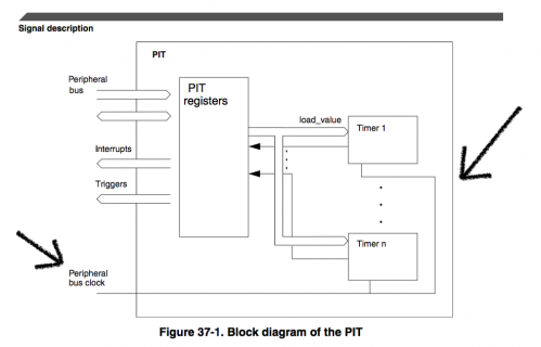
I cannot understand why the cycles to set on LDVALn (Timer Load VALue register) are dependent on F_BUS in IntervalTimer.h
Here is the line 53 taken by the file at the path Programs(x86)\Arduino\hardware\teensy\avr\cores\teensy3\IntervalTimer.h :
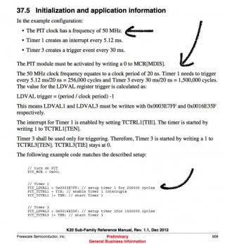
By reading at the data sheet (pag 909) it says that the period should be 20 ns = 1/50MHz:

Thus the number of cycles should NOT depend on the bus frequency, but I'm sure I missed something.
Which relation exists between the formula on the data sheet and the line of code? What am I missing?
Thanks in advance for any reply, Leo
I cannot understand why the cycles to set on LDVALn (Timer Load VALue register) are dependent on F_BUS in IntervalTimer.h
Here is the line 53 taken by the file at the path Programs(x86)\Arduino\hardware\teensy\avr\cores\teensy3\IntervalTimer.h :
Code:
uint32_t cycles = (F_BUS / 1000000) * microseconds - 1;By reading at the data sheet (pag 909) it says that the period should be 20 ns = 1/50MHz:

Thus the number of cycles should NOT depend on the bus frequency, but I'm sure I missed something.
Which relation exists between the formula on the data sheet and the line of code? What am I missing?
Thanks in advance for any reply, Leo


