Problems with below 1us IntervalTimer in Teensy 4.0

Status
Not open for further replies.

CAR

New member
Hi all,

As this is my 1st post let me introduce myself. I'm CAR, a mechanical engineer struggling to learn embedded coding and some electronics.

After learning the basics, I proposed myself to sample a 100kHz signal. To test it, I used an internal PWM of my Teensy 4.0.

To measure time, I use the IntervalTimer function included in Teenduino, nevertheless, whenever I try to sample at a frequency below 1.6us I'm unable to capture any data. Could anybody help me?

In my opinion, I'd need a sample rate of 1MHz to properly measure the signal that I intend to measure and, as far as I understood the F_BUS is 150MHz in the Teensy 4.0 so It should be more than enough.

Code:
// Fast Measure code

#include <ADC.h>
#include <ADC_util.h>

#define SAMPLES (10000)      // how many samples to combine for pp, std.dev statistics

IntervalTimer myTimer;

const byte readPin = A0; // ADC0
const byte interruptPin = 18;
const byte pwmtrig = 6;
const float init_t = 1.0;

// Volatile variables, change in the interrupt

volatile float x[SAMPLES][2];
volatile int i;
volatile float t=init_t;

ADC *adc = new ADC(); // adc object;

void setup() {

    pinMode(interruptPin, INPUT_PULLUP);
    pinMode(readPin, INPUT);
    pinMode(pwmtrig, OUTPUT);
    analogWriteFrequency(pwmtrig, 101000);
    analogWriteResolution(8); 
    analogWrite(pwmtrig, 127);

    Serial.begin(115200); //Ignored if using USB.

    ///// ADC0_Set-up /////
    // This is where we set-up the ADC.
      adc->adc0->setAveraging(1);
      adc->adc0->setResolution(10); // set bits of resolution
      adc->adc0->setConversionSpeed(ADC_CONVERSION_SPEED::HIGH_SPEED); // change the conversion speed
      adc->adc0->setSamplingSpeed(ADC_SAMPLING_SPEED::VERY_HIGH_SPEED);
    //
    ///// Timer1 Set-up /////
    // Interrupt for signal trigger
    attachInterrupt(digitalPinToInterrupt(interruptPin), TrigMeas, RISING);

}
void loop(){
  //END OF MEASURE CONDITION
    if (i == SAMPLES) 
      {
        myTimer.end();
        PrintValues();
        i = 0;
        t = 1.0;
      }
}

void TrigMeas() {
    // Here there is usually a set of intructions. Erased for clarity
      myTimer.begin(Read, init_t); // call every init_t us "ticks"
}

void Read() {
      x[i][0] = t;
      x[i][1] = analogRead(readPin);
      i = i + 1;
      t = t + init_t;
}

void PrintValues(){
      Serial.println("Time  Voltage");
      for (int i=0;i<SAMPLES;i++) {
        Serial.print(x[i][0]);
        Serial.print("  ");
        Serial.println(x[i][1]);
      }
}

Thank you very much,

CAR
 
There have been a few threads on some of this.

I have a Pull request: https://github.com/PaulStoffregen/cores/pull/425
That allows the user to change to use the higher speed bus. To get higher speeds.

But in the mean time, the Timers magic numbers were changed to allow some faster speeds
https://github.com/PaulStoffregen/cores/pull/422 (which was merged in).

I don't remember which build this made it into. But if you have not tried it you might try the latest release, which allows the T4 to have as at least as fast of Interval Timer as T3.2...

But of course everything is a trade off. That is you go for a faster clock speed than you can get faster timers, but on the other side you can not have one that is as slow... Don't remember the maximum periods of each .
 
Hi KurtE,

First of all, sorry for having to come back once again to an already solved problem!

Following, reviewing the documentation in the pull requests, I finally came to the TeensyTimerTool. I used a Tick Timer and frankly works perfect
Thanks for your answer.

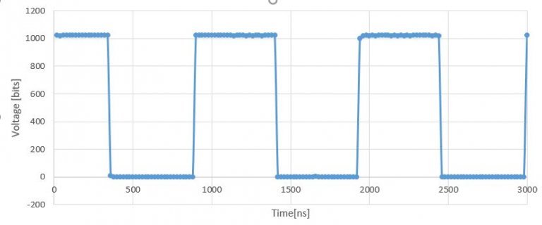
Find enclosed the solution code and a figure of the obtained resolution:

Code:
/* Example for analogRead
*  You can change the number of averages, bits of resolution and also the comparison value or range.
*/


#include <ADC.h>
#include <ADC_util.h>
#include "TeensyTimerTool.h"
using namespace TeensyTimerTool;

#define SAMPLES (10000)      // how many samples to combine for pp, std.dev statistics

Timer t1(TCK);

const byte readPin = A0; // ADC0
const byte interruptPin = 18;
const byte pwmtrig = 6;
const float init_t = 100;

// Volatile variables

volatile float x[SAMPLES][2];
volatile int i;
volatile float t=init_t/5;

ADC *adc = new ADC(); // adc object;

void setup() {

    pinMode(interruptPin, INPUT_PULLUP);
    pinMode(readPin, INPUT);
    pinMode(pwmtrig, OUTPUT);
    analogWriteFrequency(pwmtrig, 100000);
    analogWriteResolution(8); 
    analogWrite(pwmtrig, 127);
    
    Serial.begin(115200); //Ignored if using USB.

    ///// ADC0_Set-up /////
    // This is where we set-up the ADC.
      adc->adc0->setAveraging(1);
      adc->adc0->setResolution(10); // set bits of resolution
      adc->adc0->setConversionSpeed(ADC_CONVERSION_SPEED::HIGH_SPEED); // change the conversion speed
      adc->adc0->setSamplingSpeed(ADC_SAMPLING_SPEED::VERY_HIGH_SPEED);
    //
    // Interrupt for signal trigger
    attachInterrupt(digitalPinToInterrupt(interruptPin), TrigMeas, RISING);
}
void loop(){
//END OF MEASURE CONDITION
    if (i == SAMPLES) 
      {
        t1.end();
        PrintValues();
        i = 0;
        t = init_t/5;
      }
  };
void TrigMeas() {
      t1.beginPeriodic(Read, init_t); // call every init_t us/5 "ticks"
}

void Read() {
      x[i][0] = t;
      x[i][1] = analogRead(readPin);
      i = i + 1;
      t = t + init_t/5;
}

void PrintValues(){
      Serial.println("Time[ns]  Voltage[V]");
      for (int i=0;i<SAMPLES;i++) {
        Serial.print(x[i][0]);
        Serial.print("  ");
        Serial.println(x[i][1]);
      }
}

MeasuringResult.JPG
 
Last edited:
Hi CAR,

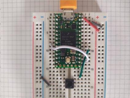
Nice work. What do you you have connected to interuptPin 18 and Pwmtrig 6? Can you show a picture of your setup or describe it?

Kind regards
 
Hi CAR,

Nice work. What do you you have connected to interuptPin 18 and Pwmtrig 6? Can you show a picture of your setup or describe it?

Kind regards

Hi Maximiljan,

As simple as it may seem, it's just a push button that triggers the interrupt.

IMG_20200329_190815_red.jpg
 
Hi Maximiljan,

As simple as it may seem, it's just a push button that triggers the interrupt.

Simple is always better.

I read your post and find myself in exactly the same position (mech. engineer learning embedded systems, etc). Up until now I have been using SDFat beta to record at 17us to SD card but the events that I am measuring last only 3 ms at most so I am very interested in hearing how your project goes and possibly moving away from SD cards myself, especially if you manage to record and capture samples at 1us successfully and would be willing to share your project later. Good luck!
 
Hi, I'm taking nowadays 10000 samples at 20ns. I don't think that I'd be able to take 50000 at that sample rate. But, you can try to adjust the sample-rate. I recommend that you read the documentation of timers of the MCU and the about the library I'm using.
https://www.pjrc.com/teensy/IMXRT1060RM_rev2.pdf
https://github.com/luni64/TeensyTimerTool

Also bear in mind thet the Teensy 4.0 has 1024K RAM so, it's not bad.

I wish you the best. I'll be posting advances in the project maybe in a dedicated post.
 
Status
Not open for further replies.
Back
Top