T4 / T4.1 RMII Signal (ethernet switch daisychain)

Status
Not open for further replies.

lucap

New member
Hi everybody

Long time looker first time poster here

I would like to daisy chain many teensy 4 or 4.1 with ethernet

The idea is to have a custom carrier board that mount a integrated switch (like this one) with 2 PHY (daisy chain IN and OUT) and the RMII connected to the teensy

From what I get the IMXRT1060RM support hardware Layer2/3, and the T4.1 has soldered on it a RMII to PHY (DP83825), then software support is given by FNET/NativeEthernet

My question is if it is possible to route the RMII signal through the GPIO pins

From the IMXRT1060RM datasheet it seem possible to remap the RMII pins, but it is not clear to me if this is actually applicable

IMHO a feature like this one would be really cool and interesting

Thanks,
Luca
 
Last edited:
My question is if it is possible to route the RMII signal through the GPIO pins

From the IMXRT1060RM datasheet it seem possible to remap the RMII pins....

The 8 RMII signals can remap to only 2 groups of pins. The other group is native pins EMC_19 to EMC_26. Unfortunately, EMC_19, EMC_20, EMC_21 have no routing to any pins. Those BGA pins simply do not have any traces bringing them to anywhere accessible on the circuit board. EMC_22 to EMC_26 are routed to the QSPI memory expansion on the bottom of the board. But those 5 aren't aren't enough.

However, the hardware has a 2nd ethernet port. I believe it is possible to get access to all 8 of its RMII signals, though one of them would require soldering a wire to the SD card. You can also get the 2 management signals. Here's the pin mapping info.

Code:
ENET2_TDATA00   Arduino 32        B0_12
ENET2_TDATA01   Arduino 29        EMC_31
ENET2_TX_EN     Arduino 28        EMC_32
ENET2_REF_CLK2  SD Card CLK       SD_B0_01
ENET2_RX_ER     Arduino 8         B1_00
ENET2_RDATA00   Arduino 7         B1_01
ENET2_RDATA01   Arduino 31 or 36  EMC_36 or B1_02
ENET2_RX_EN     Arduino 30 or 37  EMC_37 or B1_03
ENET2_MDIO      Arduino 12        B0_01
ENET2_MDC       Arduino 10        B0_00

To use this other port, you would need to rewrite the low-level code to access the other ethernet port. But the 2 ports are pretty much identical hardware, so at least in theory it should work.

Whether Teensy 4.1 RMII and this switch chip's RMII are compatible isn't something you should just assume works. The main issue to consider is the 50 MHz clock.

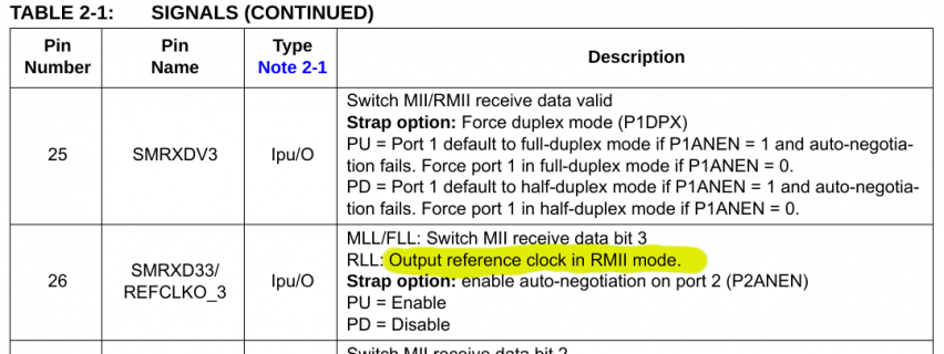
I noticed this with a quick read of the datasheet....

screenshot.png

With the connection between IMXRT1062 and DP83825 on Teensy 4.1, we configure ENET_REF_CLK2 to transmit a 50 MHz clock. That's why you don't see any separate crystal on Teensy 4.1 for the DP83825.

My guess is that switch chip probably only supports RMII where it also transmits the clock, but that impression is from only a few minutes looking at the datasheet. Obviously a connection between 2 devices both speaking RMII but each trying to transmit its own clock isn't going to work!

I believe the ethernet hardware on Teensy 4.1 could be configured to receive & use the 50 MHz clock rather than generate & transmit it. But you'd be pretty much on your own to figure out how to make that happen. There is some very old ethernet test code for Teensy 3.6 which receives the clock from a LAN8720 chip which did have a crystal (only about 80 of those ethernet boards were ever made, all hand soldered by me & Erin back when we launched Teensy 3.5 & 3.6 with a crowdfunding campaign), so maybe that could help at least a little?

If you're really good with low-level code and hardware debugging, in theory this might all be able to work. But it's a lot of unknowns to figure out and try to diagnose if it doesn't work on the 1st try.

Personally, if I were doing this project, I would just step up to a larger switch chip like KSZ8865 with has 3+ ports with the PHY built in.
 
However, the hardware has a 2nd ethernet port. I believe it is possible to get access to all 8 of its RMII signals, though one of them would require soldering a wire to the SD card. You can also get the 2 management signals. Here's the pin mapping info.

Code:
ENET2_TDATA00   Arduino 32        B0_12
ENET2_TDATA01   Arduino 29        EMC_31
ENET2_TX_EN     Arduino 28        EMC_32
ENET2_REF_CLK2  SD Card CLK       SD_B0_01
ENET2_RX_ER     Arduino 8         B1_00
ENET2_RDATA00   Arduino 7         B1_01
ENET2_RDATA01   Arduino 31 or 36  EMC_36 or B1_02
ENET2_RX_EN     Arduino 30 or 37  EMC_37 or B1_03
ENET2_MDIO      Arduino 12        B0_01
ENET2_MDC       Arduino 10        B0_00

Thank Paul!

So with the ENET2 pinout this would work with both T4 and 4.1

I'm checking some source code, at a first glance for sure it is not a plug&play solution, but with a little bit of help it seem doable to me


Thanks for the headup about the RMII clock issue

I also thinked about a phy to phy connection as defined here but this will be limited to only T4.1, but is still a possible solution


Thanks,
Luca
 
Status
Not open for further replies.
Back
Top