numero uno
Member
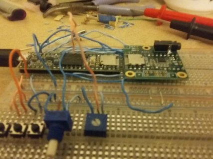
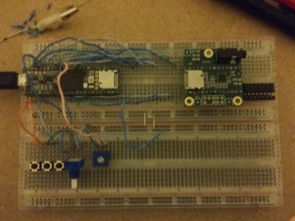
Hello, I have recently baught a teensy 3.6 board and the audio board and i soldered pins to both boards. I set up all the buttons and potentiometers the teensy 3.6, and the way I have the two boards connected is that they are both placed on a breadboard, and i have wires to connect both boards.
For connecting the two boards, I only placed wires according to where the audio pins are placed (pins 9, 11, 13, 18, 19, 22, and 23), therefore there is not a connection on every pin like there would be if the two boards were stacked on each other. I uploaded the code Part_1_02_hardware_test so that I could test if everything is working fine. The buttons work, the potentiometers work (although one of the pots are broken and give weird values when its not at 0 or vcc) so all that is left to test is the sound, but I don't get any output sound when connecting headphones. The headphones work when I plug them in the computer so i know that that is not the problem.
I tried to attach some pictures to this post that show my setup, but when i try to attach the pictures i get an error saying that the attachment failed. If anyone knows why the audio is not working please let me know, I will appreciate your help.
Thanks.
Last edited:
")