Interfacing with a modular synth

Status
Not open for further replies.
Last edited:
Hi all,


is the output from the Teensy going to match that of the DAC8552 it uses?

edit: see p.3 of this thread. the following quite probably is not correct:
not just like so, but you can set the DAC to use an external 2v5 reference, say with an LM4040 (connected to AREF), much like the ADC (i don't know though whether that's in the core library yet). otherwise it'll either be 3v3 or 1v2 (ie, when using the internal reference).


using an external reference voltage probably isn't a bad idea; it doesn't really matter with those circuits (in terms of principle), but the gain might not be quite suitable without adjusting some of the resistors (the following refers to the op amps on the right. the ones on the left, as noted in a poste further up, are there for filtering):

for example: the "uni" one (non-inverting) has 3.2x gain (determined by the two resistors R25, R26): 3.2 x 2.5v = 8v, so if setting the DAC to 3v3 (the default), you might want to lower the gain somewhat, eg. by swapping the feedback resistor (220k) to something lower: say, 150k, that would give you 2.5x gain: 2.5 x 3.3v = 8.25v.

the "bi" one is using a different configuration (inverting) and the incoming CV has 4x gain (R20, R23), so with 3v3 and appropriate offset you'd end up with +/- 6.6v, not +/- 5v; etc.

these are very basic op amp circuits (inverting resp. non-inverting amplifier/mixer), best to look it up in some textbook or on wikipedia or the like.
 
Last edited:
Thanks Mxxx —*I hope you don't think I'm being lazy! Now I understand perfectly.

It doesn't seem worth keeping the external reference voltage? It just adds more components to add in. If I can change the resistors on the opamp circuit to give me the same result anyway—
 
no, no worries. what i meant is those are basic building blocks, it's useful to get a handle on them.

using an the external reference most likely will be worth it, and it's not a big deal -- you're supposed to use a "shunt" type reference between AREF and AGND. there's a 470R resistor on the teensy, connected to 3v3. so it's just the one part.

edit: yup, those values sound right for 3v3. i'd also decrease R21 to 180k or so.
 
Last edited:
It doesn't seem worth keeping the external reference voltage? It just adds more components to add in. If I can change the resistors on the opamp circuit to give me the same result anyway—

It is worth it. Often with modular synths, oscillators which have a reputation for tuning drift or instability are directly using the voltage rails as a voltage reference (especially older ones). Don't do that. It gives you a power supply rejection ratio (PSRR) of one. Instead use a cheap, highly stable voltage reference chip which gives a vastly better PSRR, low levels of drift over temperature, and good load regulation.

There is an internal voltage reference in the teensy 3.1 but it is only 1.2 volts. If you have +5V available on the board then a 3V voltage reference can run from that.
 
It doesn't seem worth keeping the external reference voltage? It just adds more components to add in. If I can change the resistors on the opamp circuit to give me the same result anyway—

In all design, and especially with analog circuit design, there are many complex trade-offs to be made.

All analog circuitry has an undesirable effect where changes in the power supply couple to the signals. The degree to which this is suppressed is called "Power Supply Rejection Ratio", or PSRR. Even though it varies with frequency, and perhaps other changes if it's not purely linear, often for opamps a single number is given. Of course, it's spec'd at some low frequency, to make the spec better and the part more marketable. Usually the spec is in decibels, unless the part has really terrible performance, in which case the marketing folks who write the datasheet will play tricks like using a percentage, so it doesn't look so horrible, or they'll just omit that spec entirely and hope nobody notices.

Shunt style voltage references will usually have a dynamic impedance spec. It's the equivalent resistance, by ohms law, of voltage change at the reference output due to change in the series current flowing through the chip. Ideally, you'd like the power supply to be able to change quite a bit and have the reference voltage not change at all, even though the voltage on the resistor feeding it will change, so the current changes. Usually dynamic impedance is under 1 ohm. Even the LM336 (my personal favorite for a low-cost reference) is 0.2 ohm. So if you feed current to the LM336 with a 2K resistor, the change in reference voltage as the power supply fluctuates, will more-or-less be a resistor divider of 2000 to 0.2, or 80 dB PSRR.

You can further improve PSRR, at least in the audio band, by low-pass filtering. But that comes at the cost of higher source impedance, which may or may not cause more problems than any improvement it makes. Everything is a trade-off.

But if you skimp on a quality voltage reference and just use a resistor divider from the power supply, the PSRR is pretty bad. If your resistors divide by 4, that's a PSRR of only 12 dB. That 3-resistor circuit I posted yesterday will suffer this sort of issue, pretty low PSRR.

Maybe PSRR doesn't matter? You can try to low-pass filter the power, to clean it up before using it. Or if source impedance isn't a problem (it certainly matters in that 3-resistor circuit), you could low-pass filter the reference voltage too.

Or maybe whatever you're using the control voltage for won't result in terrible sound if the signal is a little (or a lot) noisy?

Everything is a trade-off. Just keep PSRR in mind. If you omit a proper voltage reference and use just resistors, noise on the power supply can much more easily couple to your signal.
 
Last edited:
I'm sold!

It also makes the selection of resistors way easier!

300k and 180k for both circuits.

EDIT: Oh wait — you mean a 3.3 ref voltage not a 3v — Still easier.
 
Last edited:
Typically you want your Vref to be a little bit lower than your voltage rail. That way, as the voltage rail moves around due to load, there is no risk that it drops lower than Vref.
 
Hmmm I can't find any 3v — or rather they're surface mount.

Can find lots of 2.5v though.

Can I also ask — what flavour of capacitor do I want to be using?
 
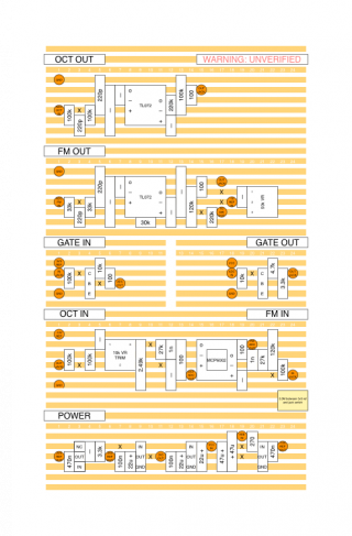
I spent an hour this morning quickly drawing this up— prototyping time!—

stripboard_v1.png
 
Last edited:
I realised a minor mistake — the DAC reference voltage is going to be 2.5v but the FM/CV inputs are designed for 3.3v… the original uses an external DAC at 2.5v but the processor still runs at 3.3
 

Hi all,


Hoping for some guidance.

I've realised that those inputs are designed for 3.3v — what would I need to do to adjust them to the 2.5 I'll end up running with?

Using my new found opamp knowledge I've calculated that it scales the voltages 0.27 for octave input and 0.2 for the FM input. I think...

Do I need to scale them to 0.2 and 0.15 respectively to get them down from 3.3 to 2.5? (Easy 20k and 100k, and 15k and 100k resistors)


James
 
Well if you don't need the extra precision, you can just read the value. You will get results in the range of about 0..775, instead of 0..1023.

I believe (but I'm not certain) that if you have a source of 2.5 volt power, you should be able to supply the 2.5v power to AREF and use analogReference (assuming it is the same as the Arduino: http://arduino.cc/en/Reference/AnalogReference). Then your analogRead would return 0..1023.
 
Hi Michael,


My issue is the other way around - my reference voltage is 2.5v but my input will be 0 to 3.3v

At least I think it will be based on the schematic.


James
 
Hi all,


Hoping for some guidance.

I've realised that those inputs are designed for 3.3v — what would I need to do to adjust them to the 2.5 I'll end up running with?

Using my new found opamp knowledge I've calculated that it scales the voltages 0.27 for octave input and 0.2 for the FM input. I think...

Do I need to scale them to 0.2 and 0.15 respectively to get them down from 3.3 to 2.5? (Easy 20k and 100k, and 15k and 100k resistors)


James


all you need to do is scale your inputs to 2.5 rather than 3.3 -- so yes, taking the negative offset in the bottom circuit as an example:

instead of -10V * 20k/120k = 1.6666666667V [ = half scale], you'd be aiming for 1.25v : eg. -10V * 15k/120k = 1.25V [ = half scale]

alternatively, you can try with a 3v0 reference à la the neutron schematic that may not be how it's supposed to be done, i gather, but apparently it works. also slightly better signal/noise ratio
 
Last edited:
all you need to do is scale your inputs to 2.5 rather than 3.3 -- so yes, taking the negative offset in the bottom circuit as an example:

instead of -10V * 20k/120k = 1.6666666667V [ = half scale], you'd be aiming for 1.25v : eg. -10V * 15k/120k = 1.25V [ = half scale]

alternatively, you can try with a 3v0 reference à la the neutron schematic that may not be how it's supposed to be done, i gather, but apparently it works. also slightly better signal/noise ratio

Thanks so much again, mxxx.

Am glad I was on the right track.

I was hoping to use a 2.5 ref voltage because I can find an LM4040 in TO92 - 3v would be better but I can't find a TO92 version.

The mutable instruments schematic uses a two 3v3 voltage regulators - run off the larger feed which I presume means it doesn't ever dip - the microprocessor runs off one and the aref off the other. I presume that would also work - but I can't a 3.3v LM4040 TO92 either.

Or else I need to look for another type.

the lm4040 doesn't exist in 3.3v, just 2.0, 2.5, 3.0, 4.096 and some larger values. mouser for example has the 3v version in the TO92 package, but i wouldn't worry too much if you can't find one/don't want to put in a large order with them. note that on the teensy there's a 470R resistor already connecting the AREF pin to 3v3, which would correspond to "Rs" in the lm4040 data sheet (or the 3k3 one in the Tides datasheet.)
 
Great — thanks!

Jim (Orgone Accumulator) has also indicated the need for the OPA2277/TLE2062 to play nicely with the Teensy.
 
Last edited:
Is there any more resolution to be had from a 3v reference compared to a 2.5v reference? I presume noise is less of an issue?

For the octave/unipolar circuit:
27/100 = 0.27 = 12*0.27 = 3.24v


I'm not sure why it's just shy of 3.3v?


If I'm going to go for 2.5v that works out as 75/300 to get 12 volts down to 2.5v — without the slight margin.


For 3v I work out:

10*(15/100) = 0.15 = 10v to 1.5v (half scale)
12*(30/120) = 0.25 = for 12v to 3v


James
 
Great — thanks!

Jim (Orgone Accumulator) has also indicated the need for the OPA2277/TLE2062 to play nicely with the Teensy.

Which I don't understand, frankly; but in practice yes, use a TL072 in there and things go wrong. Use the above op-amps (greater current drive?) and it works. It is sending a buffered, stable reference voltage into the Teensy 3.1 AREF pin.
 
Is there any more resolution to be had from a 3v reference compared to a 2.5v reference? I presume noise is less of an issue?

For the octave/unipolar circuit:
27/100 = 0.27 = 12*0.27 = 3.24v


I'm not sure why it's just shy of 3.3v?

it's just the next best thing using common resistor values, i'd say (ie 27k. the 100k from J6, as mentioned, would be fairly typical). 0.06v isn't that much, and since you'll be writing the software and get to choose what's going on, losing those few counts won't really matter.

re 3v vs 2.5v -- basically yes; both are spread over whatever the case may be: 512, 1024, 4096 etc counts. assuming the noise is the same in either case, the higher signal level will tend to be more immune from that.

where is that 12v coming from?
 
So really I would be better off using a 3.3 reference voltage of some kind as my input voltage is 12v and I have to get it down to 3.3 for the teensy anyway.

No idea why the input is 12v on that one — the spec says 0 to 8v
 
Status
Not open for further replies.
Back
Top