looking for a "joystick" breakout board

Status
Not open for further replies.

gotwake

New member
Hey gents, im new here, i was brought here by the "many axis joystick thread" and while i was looking around i am well aware that this forum is much more dedicated to the software side of things than the hardware side of things.

I am in the inital planning stages of building my own flight stick joysick.

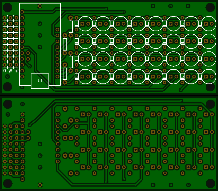
what i am hoping that one of you will be able to point me in the direction of is a breakout board that would take care of the matrixing of the buttons.


Similar to what this guy did but with the at least axis available?

interface-ready-to-go-300x186.jpg


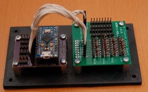
http://www.simpits.org/geneb/?p=392#more-392


everything that i am seeing for boards that do matrixing are on the output side of things rather than the input.
 
Thanks for the quick reply nominal.

It was supposed to say at least 8 axis's available. (Fat fingers)

That is a very basic version of what I am looking for. Was hoping for something with a little more. ~32 buttons and 8 axis's would be ideal.

Leo bodnar has a couple of boards available that too what I am looking for but the price is on the high end. ~$60 before shipping, but the more I look the more it is seeming that will likely be the route to go. (I don't have the knowledge or design ability to have a custom pcb printed)

http://www.leobodnar.com/shop/index.php?main_page=product_info&cPath=94&products_id=204


http://www.leobodnar.com/shop/index.php?main_page=product_info&products_id=274


(edited with links that will actually work.)
 
Last edited:
That is a very basic version of what I am looking for. Was hoping for something with a little more. ~32 buttons and 8 axis's would be ideal.
Just build it yourself, then.

Just for fun, I drew up a schematic in EasyEda for 32 buttons and 9 pots on a 94x41mm board, with headers for a Teensy LC to sit on top of; with the intent that you'd use physically separate buttons, with wires going to the board; all through-hole parts. I'm not an engineer, just a hobbyist myself. I haven't tested it, but in theory, it should work just fine. It's in public domain, so anyone can use the schematics and board files in any way they want, but on your own risk. The front and back of the board should look something like
teensy-lc-matrix.png

Teensy LC is mounted using standard male header pins on top of the board. The holes in the corners are for mounting the board.

There are 32 diodes; although I marked them BAV21, any small ones should work. The buttons should be the NO (Normally Open) type, and the two leads for each soldered to the two pads (in the respective circle).

There are four current limiting resistors; I guess something like 10k should work (max 0.33mA per output pin), but you can go as small as 1kOhm (3.3mA per output pin, which should be safe). Similarly, for the analog axes, I'd first try with 10k linear pots. The wiper is the center pin; it should also be center on the pot. In each triplet on the above board, left is ground, center wiper, and right is +3.3V. (If you swap ground and +3.3V, the pot just turns the other way.)

It would cost $2 + postage ($8 - $30) to get ten such boards from EasyEda. The resistors and diodes are pennies each, say maybe $8 total; you should get those, and the potentiometers you want, locally. Plus a Teensy LC, of course.

Also, you'd need to write the code for the Teensy LC yourself. There are useful libraries, of course, but you'd still have to write and test all the code yourself. It is fun, though.


wow thats awesome.... thank you so much for taking the time to do that.... that is exactly what i am looking for. i wish i knew how to design that myself....

Greatly appreciated
 
i wish i knew how to design that myself....
Go for it! I mean, EasyEda is very easy to use, and free; and the details for such a board are not complex.

For example, if you started reading some tutorials, checked why the circuit has current-limiting resistors (the Teensy LC pinout lists 5mA max per pin, but it is prudent to keep well under the limits) and diodes (if multiple buttons on different rows are pressed at the same time, without the diodes we'd read them wrong), then some circuit design tutorials, and definitely the EasyEda tutorial, I think you'd know enough to start.

You can start with my board design. First, peel off the "copper pours" on both top and bottom layers, by dragging one of the corners over the diagonally opposite corner, so you can see the traces. They're not that important, so they can be deleted, actually.

There's lots of helpful videos on Youtube, too. I recommend EEVblog.
 
Status
Not open for further replies.
Back
Top