Noise but no Movement with 3+ Steppers & TeensyStep

Status
Not open for further replies.

jingleby

Member
For some unknown reason when I try to run 3+ motors with TeensyStep they simply make static-ish noise and don't move (or possibly M3 does poorly). I have tried the example Array but also run into the same issue.

I have tested:
  • each of the drivers individually
  • all of the drivers as sets of 2
  • powering teensy via 5V2.4A wall adapter (in case the PC USB was the issue)
  • unplugging any individual (while unpowered) and the other 2 work and Noise is gone
  • disconnecting the 3 Drivers on the right (even though there shouldn't draw much if not being utilized)
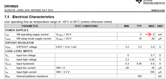
Any ideas what might be happening? Are the DRV8825 boards drawing too much for the teensy? According to the Datasheet (image below) I believe it should be way lower than the max 100ma on the 3.3V. My hunch is a grounding or drawing too much issue but not very sure at all.

Greatly appreciate any input. Thanks

2x LINKS: DRV8825 + Datasheet
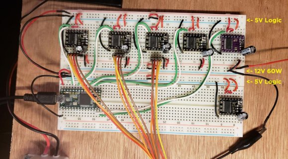
Board Layout2.jpg
DRV8825 Operating Current.PNG

Code:
#include <StepControl.h>

Stepper M1(23, 22), M2(21, 20), M3(17, 16); // create 6 motors
StepControl<> controller;

void setup() 
{
  pinMode(LED_BUILTIN,OUTPUT);
  delay(100);
  
  Stepper* motorSet_A[] = {&M1, &M2, &M3 };  // define an array of pointers to motors 1,2,5 and 6
  M1.setTargetAbs(200);                            // set targets for the motors
  M2.setTargetAbs(-500);   
  M3.setTargetAbs(-100);
//  M4.setTargetAbs(30);  
  controller.move(motorSet_A);                     // move all motors in the array to their targets

  delay(500);                                      // just to generate a nice output on the logic analyzer
 
  Stepper* motorSet_B[] = {&M1, &M3};         // another set of motors;
  M1.setTargetAbs(-110);
  M3.setTargetAbs(50);   
  controller.move(motorSet_B);                     // move set B to target

  delay(500);                                      // just to generate a nice output on the logic analyzer
 
  for (int i = 0; i < 4; i++) {                    // loop through all motors in motorSet_A...
    motorSet_A[i]->setTargetAbs(0);                // ... set targets to 0...
  }
  controller.move(motorSet_A);                     // ... and move home
}

void loop(){
  digitalWriteFast(LED_BUILTIN,!digitalReadFast(LED_BUILTIN));
  delay(100);

}
 
Also tried confirming 2 work, then adding the 3rd circuit (on a diff breadboard). For the new circuit: using the same 2 pins from one of the two 'confirmed working' motors (same signal).

Initially thought they might be getting too much (because of the noise), but or maybe its too little.

- Any sugg's on where I should probe to check volts (or mA's) of specific points?
- 3.3V issue? Possibly dropping strength for some reason and not able to fully trigger circuits?
- Several 100UF 25V capacitors ... Forgive me if i'm totally wrong, but could they absorb the incoming 12V line which is supposed to drive the motors
 
Just practicing reading the spec sheet - looks like they can run from 3.3V? And take MAX 100 micro Amp current?

Can the boards in use run from 3.3V? Being fed 5V - might have them missing the Teensy's 3.3V signal transitions?
 
Thanks for the reply. Yes, the drv8825 drivers can accept 3.3 or at least say they can.

They all work at 3.3v when running only 2 motors. Something about adding the third is pushing things begins safety margins I suspect. Draining or overloading maybe?

Would a achematic help? Ill try to find time tmrw to draw one out.
 
Okay - it looks like all is wired from 5V==Vin pin on Teensy?

Other thing - easy to do - maybe of no value - run a second GND ( and power ) from Teensy pin/Board over to the rails? Probably not relevant as I had to do that once to run a high current ESP8266 - but that might provide better GND.
 
... run a second GND ( and power ) from Teensy pin/Board over to the rails?
Do you mean basically from the same ports and to the same rails but simply another wire?

And yes, teensy is supplying Vin ... though I have also tried the regulated 3.3V 2 pins down from Vin.
 
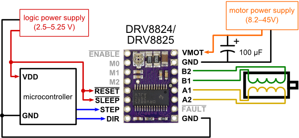
Just tried this but no luck. Should the Grounds between the motor PSU and Microcontroller be connected? The driver details don't indicate that. I suspect that is because they are optoisolated or something similar.

Also tried switching the code order of M2 and M3 to see if any "3rd" driver works. Interestingly, it is still consistent that the first 2 drivers CLOSEST to each other will fire, but the 3rd will not. I feel like this is a major insight as power may not be making it far enough along the chain.

I would love to know several areas of where to probe and what I should be looking for. Could help identify differences between what the first 2 drivers are experiencing and the 3rd.
0J4232.600.png
 
FIXED IT (But don't totally understand it).

Motor Power needs to be ran direct from the motor, not parallel (2 cables to breadboard, then off rails). 2 motors can successfully be ran in parallel, but the 3rd must add too much noise/emf.

Next question I'll have to post is how to wire this for 10x motors since power supplies don't have 10x pos/neg connections. Feel free to comment here with suggestions, though i'll post another question soon.
 
So it was power problem like I saw before - to the motors not the controllers though. I wondered because they are so low current, but wrongly assumed the motors were getting enough clean current.

If you can find a safe/clean way to Solder and insulate the power to 10 (GND and power) wires - piece of proto board perhaps or a power block with screw terminals for secure connections.
 
Yep exactly. Though I don't think perfect connections will solve it. I suspect something to restrict backflow emf before the driver (capacitor between driver and this restrictor) could do it?

I wonder if it is as simple as a diode on each line?
 
Any ideas what might be happening? Are the DRV8825 boards drawing too much for the teensy?
The 8825 boards do not need a logic supply voltage at all, they are generating it internally from the motor voltage. The only current they draw from the Teensy is via the logic pins (step/dir/mode...) which is negligible . The logic inputs work perfectly with 3.3V. Your wiring looks OK.

BTW: You have a bug in your code (but this is probably not the reason for your problem)

Code:
 for (int i = 0; i < 4; i++)  <=== you only have 3 motors in the array, so this loop will write to the nirvana
{              
    motorSet_A[i]->setTargetAbs(0);            
}
Depending on the motors / current the transition resistances of those breadboard / cable connections might generate large voltage drops @switching frequency at the drivers. Those breadboards are definitely not made for high current applications. Maybe a standard 100nF decoupling capacitor parallel to your 100µF caps will help. For testing, I'd reduce the motor current as far as possible and try it then.

Next question I'll have to post is how to wire this for 10x motors since power supplies don't have 10x pos/neg connections.

You can simply combine all the wires at the power supply you don't need separate connectors.

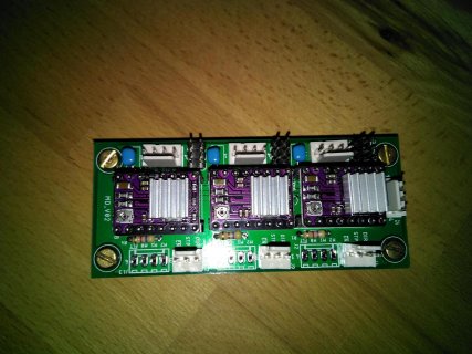
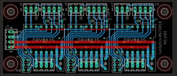
I did a small 8825-carrier carrier for 3 boards which I use for experiments. Never had any issues with power supply.

IMG_20181223_095510_941.jpg md.jpg

I got 10pcs for about EUR20 including shipment from ITEAD. Drop me a note if you need the gerbers or the eagle files.
 
This is great, thanks. I'll certainly consider PCB's on a future iteration.

I'm moving everything over from bboards to protoboards this week. Fingers crossed the recable and 12v to 24v change doesn't break anything (like earlier).

I'll give the rotational update a try too! Does using the float speed modifier require an additional timer, or since its a derivative of the parent it's only 1?
 
I'll give the rotational update a try too! Does using the float speed modifier require an additional timer, or since its a derivative of the parent it's only 1?
Nothing changed timer wise. I.e., 1 PIT + 2FTM channels per motor controller. Up to 10 motors per controller.
 
Status
Not open for further replies.
Back
Top