BradleyC
Active member
This is an RS485 half-duplex application where I am trying to reverse engineer existing behavior in a multi-zone home AC system.
The Teensy is connected to a working home AC system and is able to correctly receive and to transmit functioning command and response frames.
However, it cannot receive anything after it has transmitted (used Serial1.write()) even just one byte! (Serial1.available() always returns 0 until the MCU is rebooted.)
I cannot figure out why after trying many things (register dumps) and studying both the NXP reference and the device driver files, so I am posting this to seek help.
Thank you in advance for any specific or general guidance.
This is very frustrating because it should work but it doesn't.
I think I must be missing some important detail regarding half-duplex protocol/hardware. I hope it's that simple.
Note: I have also used polling in the loop() for reading packets but this example uses serialEvent1() to do the read of bytes. The receive lockup occurs in either mode of reception immediately after the Serial1.write() function is called.
Hardware: Teensy 3.2, MAX483 transceiver.
Software: Arduino 1.85, Teensyduino 1.41
Development System: Windows 7 64 bit SP 1
Supplemental Attachments
The Teensy is connected to a working home AC system and is able to correctly receive and to transmit functioning command and response frames.
However, it cannot receive anything after it has transmitted (used Serial1.write()) even just one byte! (Serial1.available() always returns 0 until the MCU is rebooted.)
I cannot figure out why after trying many things (register dumps) and studying both the NXP reference and the device driver files, so I am posting this to seek help.
Thank you in advance for any specific or general guidance.
This is very frustrating because it should work but it doesn't.
I think I must be missing some important detail regarding half-duplex protocol/hardware. I hope it's that simple.
Note: I have also used polling in the loop() for reading packets but this example uses serialEvent1() to do the read of bytes. The receive lockup occurs in either mode of reception immediately after the Serial1.write() function is called.
Code:
// Teensy 2.0 has the LED on pin 11
// Teensy++ 2.0 has the LED on pin 6
// Teensy 3.x / Teensy LC have the LED on pin 13
// For thermostat testing I have added an LED on unused pin 2 with a 1K OHM resistor to ground.
const int ledPin = 2;

uint32_t  frameCount = 0;
uint8_t byteCount = 0;

#define MAX483CTL 9             // Pin 9 controls MAX483 direction. LOW enables Reception, HIGH, transmission
// the setup() method runs once, when the sketch starts
void setup() {
  // initialize the digital pin as an output.
  pinMode(ledPin, OUTPUT);
  digitalWrite(ledPin, LOW);
  Serial.begin(115200);
  delay(1000);

  // the HVAC controls RS-485 subsystem runs at 19200, 8N1.
  Serial1.begin( 19200 );
  Serial1.transmitterEnable( MAX483CTL ); // Pin 9 controls MAX483 direction. LOW enables Reception, HIGH, transmission

  delay(1000);
  Serial.println("\r\nsetup() complete");
}


// the loop() method runs over and over again,
// as long as the board has power

void loop() {
  static uint32_t norcvdata = 0;
  static bool sent = false;

  digitalWrite(ledPin, sent ? LOW : HIGH ); // show when the reset packet has been sent.

  if ( 0 == Serial1.available() && !sent ) {
    if ((byteCount == 8) && (frameCount == 25)) {
      // after receiving all of the 25th frame, and while the bus is quiescent
      // transmit one reset unit command to thermostat number 04 (study)
      sendReset();
      sent=true;  // do this only once because there is no reception after this and byteCount remains 8, and frameCount remains 50!
    }
  }
}

void sendReset( void ) {
  // after receiving all of the 50th frame, and while the bus is quiescent
  // transmit one reset unit command to thermostat number 04 (study)
  Serial1.write(0xFF);  //
  Serial1.write(0x04);  // dst = Study
  Serial1.write(0x06);  // src = prototype (this node)
  Serial1.write(0x6E);  // cnd = reset unit (reboot the Study thermostat)
  Serial1.write(0x00);  // pad frame to 8 bytes
  Serial1.write(0x00);  // pad frame to 8 bytes
  Serial1.write(0x00);  // pad frame to 8 bytes
  Serial1.write(0x00);  // pad frame to 8 bytes

  Serial.println("\r\n>>> FF 04 06 6E 00 00 00 00 ");
}
// serialEvent1() is a call-back that is called when receive char interrupt occurs.
// I'm not sure if it is invoked at interrupt level but it is called even before
// the loop begins

// Print each received byte on the monitor output
// Do so in a way that lists each 8 byte Frame, beginning with the
// 0xFF StartOfFrame byte, on a separate line.

void serialEvent1( void ) {
  int dataByte;

  int bytesAvailable = Serial1.available(); // with the AC controls running,  the value 4 is always returned here.

  if (bytesAvailable > 0 ) {

    while( bytesAvailable-- ) {
      dataByte = Serial1.read();
      if (-1 == dataByte ) {
        Serial.println("Fault");
        return;
      } else {
        // No error
        if (0xFF == (uint8_t)dataByte) {
          byteCount = 1;
          Serial.println();
          Serial.print(++frameCount);
          Serial.print(": FF ");
          return;
        } else {
          byteCount++;
        }
        if (0 ==(0xF0 & (uint8_t)dataByte)) {
          Serial.print("0");
        }
        Serial.print((uint8_t)dataByte, HEX);
        Serial.print(" ");
      }
    }

  } else {
    // Not really sure why this should be here or if it should be here but saw
    // it suggested in the Teensy forum.
    Serial1.flush(); // wait for outstanding transmits to complete.
  }


}
Hardware: Teensy 3.2, MAX483 transceiver.
Software: Arduino 1.85, Teensyduino 1.41
Development System: Windows 7 64 bit SP 1
Supplemental Attachments
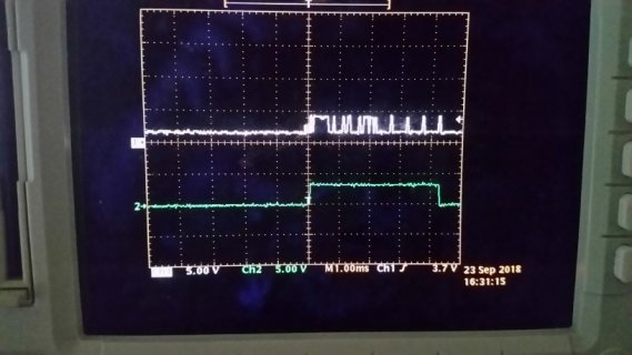
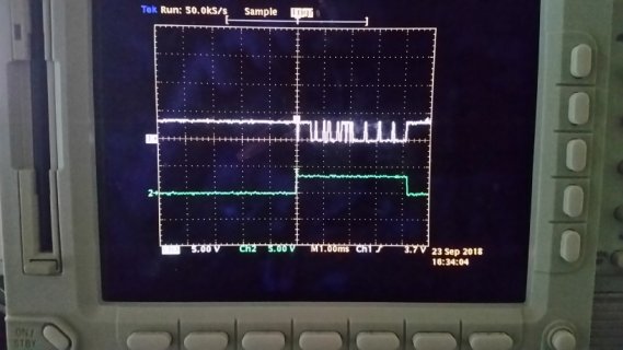
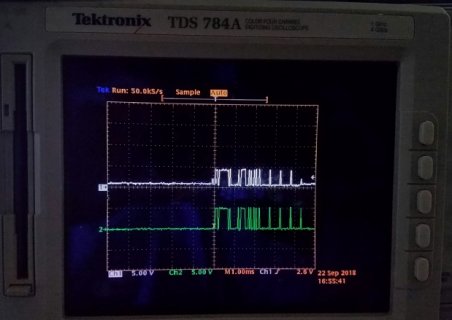
- A photo of the scope display showing the input signals to the teensy module. The green trace is USART0 Rx Pin with 5V amplitude because the MAX483 is powered by 5.0V. The white trace is the A side, non-inverted signal, (pin 6 of the MAX483) of the RS485 bus. I assume these look normal but this is my first RS485 engineering experience. This trace of one frame appears the same before and after the send of the reset frame (using 4 Serial1.write() calls). So I believe the failure is inside the code within the Teensy, not the circuitry outside.
- A hand-drawn Visio schematic of my Teensy 3.2 RS485 subsystem circuitry.
- For context, a schematic of the home AC system showing controller and multiple thermostats.
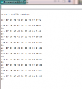
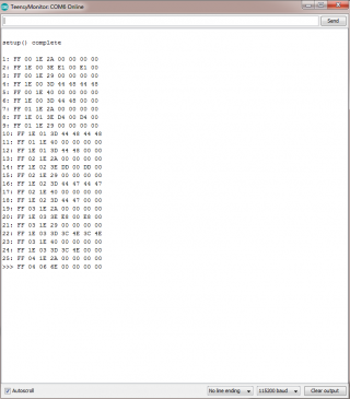
- A screen capture of the serial monitor output of the sketch showing 25 good frames received from the RS485 network but none after the transmit from the teensy.
Attachments
Last edited: