
You are using an out of date browser. It may not display this or other websites correctly.
You should upgrade or use an alternative browser.
You should upgrade or use an alternative browser.
Teensy 4.1 - do I need other board with 2 cores to solve my problem?
- Thread starter Fiskusmati
- Start date
- Status
- Not open for further replies.
Fiskusmati
Active member
Indeed this is correct. The 1062 was changed to FAST GPIO mode and that invalidates access using GPIO1-4 and moves them to GPIO6-9 for access unless the FAST IO setting is undone.
The imxrt.h file contains function macro information for access to those pins as GPIO6,7,8,9
So how it is possible that I can still access GPIO1-4 with success and with no compilation errors? I have not modified teensyduino. I use newest teensyduino and IDE 1.8.12
But thank you for information, I will now use GPIO6-9
PaulStoffregen
Well-known member
So how it is possible that I can still access GPIO1-4 with success and with no compilation errors?
Not sure if I would use the word "success" to describe reading registers that don't actually give you any useful results.
But consider the compiler's point of view. This hardware has 2 different groups of registers which can access the same physical pins. Another set of registers configures each pin, to assign it either the slow GPIO1-4 or to the fast GPIO6-9. The compiler doesn't "know" which pins are assigned to the slow vs fast GPIO. They can be reassigned while the processor is running, so even a very advanced static code analysis (which the compiler does not do) could not reliably determine which registers are proper. Since each pin is dynamically assignable, you can configure the hardware for a scenario where some pins in the GPIO1 group are accessed with GPIO6 and others are accessed by GPIO1. Semantically, accessing either or both sets of GPIO is perfectly legal. That's why you don't get a compile error.
Using slow GPIO might seem silly when fast GPIO is available. Indeed that is why we default all the pins to using the fast GPIO on Teensy 4.0 & 4.1.
But DMA can not access GPIO6-9. FlexIO3 is also inaccessible to DMA, because like the fast GPIO, it's on a different bus which doesn't have DMA access. Fortunately for GPIO, if you need to use DMA to control a pin, you can dynamically change the assignment for that pin back to the slow GPIO. The OctoWS2811 library does this, where timers connected to the crossbar trigger cause DMA which writes to the GPIO1-4 registers to synthesize waveforms. The point is we do actually use the dynamic assignment of pins between GPIO1-4 and GPIO6-9 in special scenarios like this. Those slow-but-DMA-accessible GPIO1-4 registers need to be syntactically valid for this sort of code to work.
Why NXP designed the chip this way involves some guesswork, since they don't usually document how things are designed internally. We do know the earlier 1052 chip which we used for beta testing in the first half of 2019 had only the slow GPIO. I'm imagining NXP heard complaints from large customers (like General Motors size "large") about how slow the GPIO was. NXP probably didn't intend for it to be so slow. Probably nobody really put much thought into the GPIO speed. They get the Cortex-M7 core from ARM, and for reasons unknown configured the AXI bus to run at 1/4 the CPU clock speed. Then there's at least 1, maybe 2 bus bridges between AXI bus and the GPIO peripheral (very likely AXI to AHB to APB... but again, much guesswork here). All this stuff is designed with standard buses have handshakes that add wait states if needed. My guess is engineers just put stuff on buses and compiled the verilog or whatever HDL they use.
In the 1062 chip, NXP added GPIO6-9. The (almost certainly) connected it to the M7's AHBP bus.

This diagram is from ARM's documentation (google for DDI0489B). Inside the 1062, we know that almost everything is connected to the AXI bus. By default we divvy up the RAM1 bank (512K) into ITCM and most variables into DTCM so code runs as fast as possible. The RAM2 bank and almost all peripherals are accessed over AXI, which is slower. As far as I know, GPIO6-9 and FlexIO3 are the only things connected to the fast AHBP bus.
The AHBS bus is only for DMA to be able to access variables and code in ITCM and DTCM. Why ARM didn't also give it the ability to access peripherals over AHBP is a mystery to me. But that's the way they designed Cortex-M7.
How NXP designed the GPIO connections is also a matter of guesswork. But we do know they were added between 1052 and 1062. 1052 had only the slow GPIO. From the timing of those 2 chip releases, it's probably reasonable to assume they didn't do any major new design in such a short time frame. My guess is they created 2-input instances of the pin muxes as a quick solution to avoid much change elsewhere in the already-proven 1052 design. It probably would have made more sense to just expand the number of inputs on the normal pin muxes and assign GPIO1 to the normal ALT5 channel and put GPIO6 on another channel of that normal pin mux. But that's not what they did. Instead we get both GPIO1 or GPIO6 selected by the ALT5 pin mux, and they there's a 2nd not-as-well-documented mux which physically connects the actual pin to either GPIO1 or GPIO6.
When GPIO1 doesn't have access to the pin (which is the way Teensyduino's startup code configures the hardware), the result of accessing GPIO1 is the same as if the pin mux assigned the pin to one of the other peripherals. You can still use GPIO1 or GPIO6 to try to access the pin, but reading always gives 0 and writing has no effect, because the pin mux is routing the actual pin to something else like a serial port, I2C, SPI, etc.
So that's why you can still access GPIO1-4 with "success". Well, at least with the caveat of quite a lot of guesswork about how NXP designed the chip.
Fiskusmati
Active member
Thank you for explanation.
I wrote success because reading GPIO1 still gives me the same information as GPIO6. I tested it. Pin states change in GPIO1 register accordingly to external inputs, but as you said probably much slower (I have not tested for speed).
I wrote success because reading GPIO1 still gives me the same information as GPIO6. I tested it. Pin states change in GPIO1 register accordingly to external inputs, but as you said probably much slower (I have not tested for speed).
boxxofrobots
Well-known member
Why not use 4 8 bit shift registers to dma clock the input from your A/D convertors through the SPI port?
el_supremo
Well-known member
FYI: Accessing GPIO6_PSR takes 10 cycles. Getting the same info from GPIO1_PSR takes up to 30 cycles - it varies from 27 to 30.
Pete
Pete
Fiskusmati
Active member
Hello.
Because I needed to minimize bit manipulation for fast operation, pins I have selected as ADC inputs are from GPIO6 and GPIO7 groups. I'm using 2x14bit ADC now (so 28pins used).
Unfortunately now I need to use SPI interface also, and pins for SPI and SPI1 shown in teensy 4.1 pinout card have been already used as ADC inputs.
Am I now left with Software SPI, or can I still assign any pins for hardware SPI?
MichaelMeissner
Senior Member+
Hello.
Because I needed to minimize bit manipulation for fast operation, pins I have selected as ADC inputs are from GPIO6 and GPIO7 groups. I'm using 2x14bit ADC now (so 28pins used).
Unfortunately now I need to use SPI interface also, and pins for SPI and SPI1 shown in teensy 4.1 pinout card have been already used as ADC inputs.
Am I now left with Software SPI, or can I still assign any pins for hardware SPI?
Are you using either the micro-SD card or the psram/flash memory pads underneath the Teensy 4.1?
If you aren't using the micro-SD card, you could use something like this to bring out the SD pins:
And the two sets of solder pads underneath the Teensy use FlexSPI. I don't know if that would work for your purposes.
Fiskusmati
Active member
Are you using either the micro-SD card or the psram/flash memory pads underneath the Teensy 4.1?
If you aren't using the micro-SD card, you could use something like this to bring out the SD pins:
And the two sets of solder pads underneath the Teensy use FlexSPI. I don't know if that would work for your purposes.
I think SD card in teensy 4.1 is not SPI driven. Could you explain your ideas a little bit more?
Fiskusmati
Active member
In other words: what pins can be assigned to:
SPI.setMOSI(pin)
SPI.setMISO(pin)
SPI.setSCK(pin)
?
SPI.setMOSI(pin)
SPI.setMISO(pin)
SPI.setSCK(pin)
?
Fiskusmati
Active member
MichaelMeissner
Senior Member+
I think SD card in teensy 4.1 is not SPI driven. Could you explain your ideas a little bit more?
Sure, in the Teensy 4.0 the micro SD pins are listed as:
- Pad 34 (MISO2)
- Pad 35 (MOSI2)
- Ground
- Pad 36 (CS2)
- 3.3 volt
- Pad 37 (SCK2)
- Pad 38
- Pad 39
In Teensy 4.1, the micro SD card pins got renamed to 42-47, but the layout should be the same, since in both cases it is what micro SD card readers use.
I recall in the Teensy 4.0/4.1 lists, there were some mention of using these pads for normal SPI (not quad SPI like the micro SD card and memory chips use). I vaguely recall KurtE, defragster, or mjs513 connecting a display to the 4.0 SPI pins.
I similarly recall some recent discussion about using the memory pads, but I don't recall if anybody did that.
defragster
Senior Member+
The T_4.1 onboard SD socket is directly connected to specific pins not exposed elsewhere and will not conflict. They are connected to a 4 bit data SDIO bus independent of other SPI pins or hardware. Use of that interface takes indication to code built into the SD library like PJRC SD or others {grieman} do. This is the same as developed for the T_3.6.
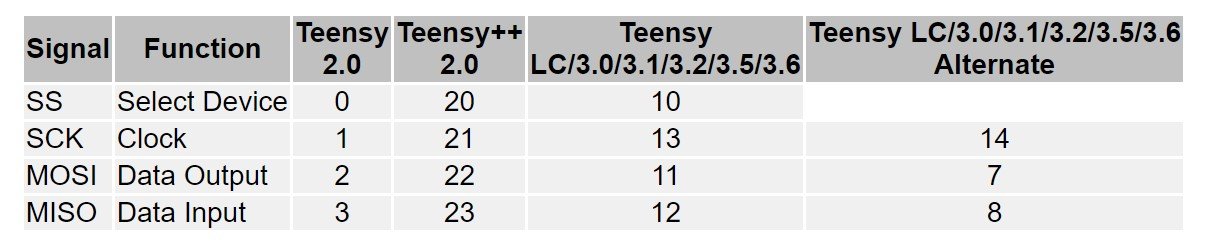
The card { with Teensy or online at PJRC.com } shows the SPI pins and their association - internal processor pin arrangement does not allow ALTernative pins like some other Teensy do.
The card { with Teensy or online at PJRC.com } shows the SPI pins and their association - internal processor pin arrangement does not allow ALTernative pins like some other Teensy do.
MichaelMeissner
Senior Member+
In other words: what pins can be assigned to:
SPI.setMOSI(pin)
SPI.setMISO(pin)
SPI.setSCK(pin)
?
The Teensy 4.1 does NOT have alternate pins for the SPI buses, except for using SPI1.SetMISO(1) instead of using pin 39.
<edit>
Note, I left out the word NOT in the above sentence.
Last edited:
Fiskusmati
Active member
I know that teensy 4.1 has alternate pins but I don't know which they are.
I'm currently using pins listed below for adc reading.
Are there any pins left that can be assigned so I have one working SPI interface?
I'm currently using pins listed below for adc reading.
Are there any pins left that can be assigned so I have one working SPI interface?
Code:
  pinMode(19, INPUT_PULLUP);
  pinMode(18, INPUT_PULLUP);
  pinMode(15, INPUT_PULLUP);
  pinMode(14, INPUT_PULLUP);
  pinMode(40, INPUT_PULLUP);
  pinMode(41, INPUT_PULLUP);
  pinMode(17, INPUT_PULLUP);
  pinMode(16, INPUT_PULLUP);
  pinMode(22, INPUT_PULLUP);
  pinMode(23, INPUT_PULLUP);
  pinMode(20, INPUT_PULLUP);
  pinMode(21, INPUT_PULLUP);
  pinMode(38, INPUT_PULLUP);
  pinMode(39, INPUT_PULLUP);

  pinMode(26, INPUT_PULLUP);
  pinMode(27, INPUT_PULLUP);
  pinMode(10, INPUT_PULLUP);
  pinMode(12, INPUT_PULLUP);
  pinMode(11, INPUT_PULLUP);
  pinMode(6, INPUT_PULLUP);
  pinMode(9, INPUT_PULLUP);
  pinMode(32, INPUT_PULLUP);
  pinMode(8, INPUT_PULLUP);
  pinMode(7, INPUT_PULLUP);
  pinMode(36, INPUT_PULLUP);
  pinMode(37, INPUT_PULLUP);
  pinMode(35, INPUT_PULLUP);
  pinMode(34, INPUT_PULLUP);
MichaelMeissner
Senior Member+
I know that teensy 4.1 has alternate pins but I don't know which they are.
I'm currently using pins listed below for adc reading.
Are there any pins left that can be assigned so I have one working SPI interface?
As far as I know, the only alternates are pin 0 or pin 38 being the preferred CS1 pin, and pin 1 or pin 39 being the MISO1 pin. So, the answer is no, with the outer row pins you've used, there is no hardware SPI.
Fiskusmati
Active member
Thanks for reply.
Does anyone know what pins are brought there:

There is no information about purpose of this pads.
Does anyone know what pins are brought there:
There is no information about purpose of this pads.
KurtE
Senior Member+
Those pins are the same as the T4 pins that are on the outside of board... And almost identical to the pins on T3.6/T3.5 at those exact positions.
That is On/Off, Program, GND 3.3V and VBat... The difference to T3.6/3.5 is the ON/OFF pad replaced the Reset pad.
As mentioned there are very few alternate SPI pins. As also probably mentioned there are more than one SPI...
But to use them, you use the individual objects: SPI, SPI1, SPI2.
And in most cases like this, I end up looking at the source code... But then again I was involved in it.
Example the hardware description data for the SPI object:
Yes most of this looks random: but I see, that
The only MISO is 12, MOSI os 11 SCK is 13 and it has 3 chip select pins 10 37 36. Note these CS pins are very different that T3.x...
And likewise SPI1:
MISO(1, 39), MOSI(26), SCK(27), and two CS pins (0, 38).
Edit: Should also mention SPI2 has MISO, MOSI, SCK pins on both the SDCard pins as well as the back memory pins.
Sorry I have not fully gone back through all of this thread to know what it is you need. There is also a possibility of additional logical SPI objects, using FlexIO. I have a working version, but as it does not build from the same base class, it is a little more difficult to substitute in as a replacement.
That is On/Off, Program, GND 3.3V and VBat... The difference to T3.6/3.5 is the ON/OFF pad replaced the Reset pad.
As mentioned there are very few alternate SPI pins. As also probably mentioned there are more than one SPI...
But to use them, you use the individual objects: SPI, SPI1, SPI2.
And in most cases like this, I end up looking at the source code... But then again I was involved in it.
Example the hardware description data for the SPI object:
Code:
#if defined(ARDUINO_TEENSY41)
const SPIClass::SPI_Hardware_t  SPIClass::spiclass_lpspi4_hardware = {
	CCM_CCGR1, CCM_CCGR1_LPSPI4(CCM_CCGR_ON),
	DMAMUX_SOURCE_LPSPI4_TX, DMAMUX_SOURCE_LPSPI4_RX, _spi_dma_rxISR0,
	12, 255,  // MISO
	3 | 0x10, 0,
	0, 0,
	IOMUXC_LPSPI4_SDI_SELECT_INPUT,
	11, 255, // MOSI
	3 | 0x10, 0,
	0, 0,
	IOMUXC_LPSPI4_SDO_SELECT_INPUT,
	13, 255, // SCK
	3 | 0x10, 0,
	0, 0,
	IOMUXC_LPSPI4_SCK_SELECT_INPUT,
	10, 37, 36, // CS
	3 | 0x10, 2 | 0x10, 2 | 0x10,
	1, 2, 3,
	0, 0, 0,
	&IOMUXC_LPSPI4_PCS0_SELECT_INPUT, 0, 0
};
#elseThe only MISO is 12, MOSI os 11 SCK is 13 and it has 3 chip select pins 10 37 36. Note these CS pins are very different that T3.x...
And likewise SPI1:
Code:
#if defined(ARDUINO_TEENSY41)
const SPIClass::SPI_Hardware_t  SPIClass::spiclass_lpspi3_hardware = {
	CCM_CCGR1, CCM_CCGR1_LPSPI3(CCM_CCGR_ON),
	DMAMUX_SOURCE_LPSPI3_TX, DMAMUX_SOURCE_LPSPI3_RX, _spi_dma_rxISR1,
	1, 39,
	7 | 0x10, 2 | 0x10,
	0, 1,
	IOMUXC_LPSPI3_SDI_SELECT_INPUT,
	26, 255,
	2 | 0x10, 0,
	1, 0,
	IOMUXC_LPSPI3_SDO_SELECT_INPUT,
	27, 255,
	2 | 0x10, 0,
	1,  0,
	IOMUXC_LPSPI3_SCK_SELECT_INPUT,
	0, 38, 255,
	7 | 0x10, 2 | 0x10, 0,
	1, 1, 0,
	0, 1, 0,
	&IOMUXC_LPSPI3_PCS0_SELECT_INPUT, &IOMUXC_LPSPI3_PCS0_SELECT_INPUT, 0
};Edit: Should also mention SPI2 has MISO, MOSI, SCK pins on both the SDCard pins as well as the back memory pins.
Sorry I have not fully gone back through all of this thread to know what it is you need. There is also a possibility of additional logical SPI objects, using FlexIO. I have a working version, but as it does not build from the same base class, it is a little more difficult to substitute in as a replacement.
Fiskusmati
Active member
Those pins are the same as the T4 pins that are on the outside of board... And almost identical to the pins on T3.6/T3.5 at those exact positions.
That is On/Off, Program, GND 3.3V and VBat... The difference to T3.6/3.5 is the ON/OFF pad replaced the Reset pad.
As mentioned there are very few alternate SPI pins. As also probably mentioned there are more than one SPI...
But to use them, you use the individual objects: SPI, SPI1, SPI2.
And in most cases like this, I end up looking at the source code... But then again I was involved in it.
Example the hardware description data for the SPI object:
Yes most of this looks random: but I see, thatCode:#if defined(ARDUINO_TEENSY41) const SPIClass::SPI_Hardware_t SPIClass::spiclass_lpspi4_hardware = { CCM_CCGR1, CCM_CCGR1_LPSPI4(CCM_CCGR_ON), DMAMUX_SOURCE_LPSPI4_TX, DMAMUX_SOURCE_LPSPI4_RX, _spi_dma_rxISR0, 12, 255, // MISO 3 | 0x10, 0, 0, 0, IOMUXC_LPSPI4_SDI_SELECT_INPUT, 11, 255, // MOSI 3 | 0x10, 0, 0, 0, IOMUXC_LPSPI4_SDO_SELECT_INPUT, 13, 255, // SCK 3 | 0x10, 0, 0, 0, IOMUXC_LPSPI4_SCK_SELECT_INPUT, 10, 37, 36, // CS 3 | 0x10, 2 | 0x10, 2 | 0x10, 1, 2, 3, 0, 0, 0, &IOMUXC_LPSPI4_PCS0_SELECT_INPUT, 0, 0 }; #else
The only MISO is 12, MOSI os 11 SCK is 13 and it has 3 chip select pins 10 37 36. Note these CS pins are very different that T3.x...
And likewise SPI1:
MISO(1, 39), MOSI(26), SCK(27), and two CS pins (0, 38).Code:#if defined(ARDUINO_TEENSY41) const SPIClass::SPI_Hardware_t SPIClass::spiclass_lpspi3_hardware = { CCM_CCGR1, CCM_CCGR1_LPSPI3(CCM_CCGR_ON), DMAMUX_SOURCE_LPSPI3_TX, DMAMUX_SOURCE_LPSPI3_RX, _spi_dma_rxISR1, 1, 39, 7 | 0x10, 2 | 0x10, 0, 1, IOMUXC_LPSPI3_SDI_SELECT_INPUT, 26, 255, 2 | 0x10, 0, 1, 0, IOMUXC_LPSPI3_SDO_SELECT_INPUT, 27, 255, 2 | 0x10, 0, 1, 0, IOMUXC_LPSPI3_SCK_SELECT_INPUT, 0, 38, 255, 7 | 0x10, 2 | 0x10, 0, 1, 1, 0, 0, 1, 0, &IOMUXC_LPSPI3_PCS0_SELECT_INPUT, &IOMUXC_LPSPI3_PCS0_SELECT_INPUT, 0 };
Edit: Should also mention SPI2 has MISO, MOSI, SCK pins on both the SDCard pins as well as the back memory pins.
Sorry I have not fully gone back through all of this thread to know what it is you need. There is also a possibility of additional logical SPI objects, using FlexIO. I have a working version, but as it does not build from the same base class, it is a little more difficult to substitute in as a replacement.
Thank you for reply.
I will reorganize parallel ADC pins to free 26 and 27 (1,0 are already free). It will require some changes in hardware and additional bit manipulation but for now it will be much easier for me.
Swarfmaker
Member
I would like to write data to Port 1 (I guess I would actually write to Port 6, based on what I've read in this thread).
Where do I find documentation for how to do this?
According to the PJRC.com web site, I'm supposed to use Teensyduino for programming. But, it really doesn't mention the 4.1 specifically. Is this the correct program to use?
I'm familiar with the standard Arduino, and I understand that there are differences between that and the Teensy 4.1. For the purposes of programming, is there a source or web site that documents what I need to know?
Swarfmaker
Member
I think I found part of the answer I was looking for. Once I figured out what terms to search for, I found this thread, and I think it answers my question about what syntax I need to write to GPIO6.
https://forum.pjrc.com/threads/61442-Teensy-4-1-8-Bit-Parallel-I-O
The answer is: GPIO6_DR = (GPIO6_DR & ~(0xFCF3 << 12)) | ((data & 0xFCF3) << 12);
But how do you know that the correct syntax is "GPIOn_DR = X"? I'm sure there are other things like this that I'll need to know and I don't want to bother you all with such simple questions.
Last edited:
KurtE
Senior Member+
@swarfmaker - I am guessing from your posts on other thread you are talking about GPIO pins?
Teensyduino is obviously the simplest way to talk to Teensy boards.
Again there is no context here on what you are asking?
The simplest ways read/write GPIO pins is to use: digitalWrite (or digitalWriteFast), digitalRead...
Now if you are asking about how to access all of the pins on one IO PORT. I would suggest if you have not already done so, that you download the Reference Manual for the different boards you have.
In this case T4.1/T4 are the same and you can find them up at: https://www.pjrc.com/teensy/datasheets.html
Chapter 12 describes GPIO including the actual registers.
When you install teensyduino, the core files for the T4/T4.1 are installed in: <where your arduino is installed>/hardware/teensy/avr/cores/teensy4
if you look at the file: imxrt.h
It has defines for hopefully every register defined by these chips.
So for example to talk to the Data Register of GPIO6 you will find: the define: GPIO6_DR
so you could set all of the GPIO pins output to 0 by: GPIO6_DR = 0;
(Actually I am surprised we have not created a structure for GPIO yet...) Maybe will at some point, like we have done for many other subsystems.
Swarfmaker
Member
Thanks for the response.
Yes, I am looking at sending out parallel data, 8-bits simultaneously. The thread I linked to in my previous message addressed the exact issue I was looking for.
I have already downloaded the manual for the 4.1. But it is massive. It is 3437 pages. I'm finding it difficult to wade through and I probably only need a small subset of the information contained in it to do my simple project.
Since the Teensy is marketed as being an Arduino-type device, I was hoping to find some less overwhelming documentation for doing common tasks.
For an example, I saw a code fragment that used "GPIO9_DR_TOGGLE = X". That seems like it would be a rather handy command for some situations. But how do you use it? What exactly does it do? Where did that come from? How would I have been able to find out about it without seeing it in someone else's program? How do people know about these things? And I'm sure there are many more .
I'll take a look at the header files.
It looks like I can use GPIO6 for parallel output. I noticed that one of the pins, 1.5, is grounded. What happens if I turn on this bit?
PaulStoffregen
Well-known member
Since the Teensy is marketed as being an Arduino-type device, I was hoping to find some less overwhelming documentation for doing common tasks.
The less overwhelming way exists. It's called digitalWrite(). We also have digitalWriteFast() which is easy to understand and much faster, at the expense of not fully emulating the old AVR semantics (like writing while using input mode controls the pullup resistor). Hopefully using pinMode() to configure the pin and then either digitalWrite() or digitalWriteFast() is indeed easy to understand?
But you keep insisting on direct access to the underlying hardware registers. You can do that too on Arduino. But if you want to write to the hardware registers, just like regular Arduino, you need the chip's datasheet or reference manual. These newer and much more powerful chips have far more features, which means the manual has many more pages.
In these newer chips, configuring the pin is indeed more complicated. But once configured, the GPIO registers work pretty much the same way as AVR and other chips (newer AVR chips have the registers where writing 1 sets or clears or toggles a bit, writing 0 leaves that bit unchanged). The main issue is only 32 bit writes are supported. Otherwise the GPIO registers are very similar, regardless of how many other pages are in the rest of the manual.
Last edited:
PaulStoffregen
Well-known member
For an example, I saw a code fragment that used "GPIO9_DR_TOGGLE = X". That seems like it would be a rather handy command for some situations. But how do you use it? What exactly does it do? Where did that come from? How would I have been able to find out about it without seeing it in someone else's program? How do people know about these things? And I'm sure there are many more .
Like all the GPIO registers, it's documented in chapter 12. That particular register is documented on page 979, and it's shown in the list of all registers on page 962.
Yeah, the whole manual is huge. But chapter 12 is just 31 pages.
- Status
- Not open for further replies.