What is the exact Crystal teensy 3.2 uses?

Status
Not open for further replies.

russdx

Well-known member
I have made hundreds of custom teensy boards using a through hole Crystal with 2 load caps and they are all fine. I have now swapped to a smd crystal without the load caps and have had 2 out of 25 boards just die for no reason. The new boards are a totally new pcb layout but identical schematic to the previous through hole Crystal design.

I can only assume i have picked a wrong Crystal (16mhz,10pf) or my pcb layout is wrong? (no traces under Crystal, its right next to the mk20, has ground plane around / under it)

Cant think why these to boards worked great for two days then just died. They both still create 3.3v but apart from that there is no life.


My next step is to use the exact same Crystal the real teensy 3.2s use.

I can post schematics and board layout if needed.

Crystal used:
ABM8G-16.000MHZ-4Y-T3
http://www.mouser.com/ds/2/3/ABM8G-10572.pdf

Just noticed iv not connected the crystal GND (as the first crystal i selected did not require this, could this be the reason for micro dying?)

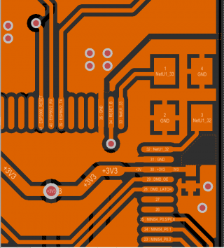
Here is top layer on pcb (nothing is on bottom layer under crystal apart from GND plane
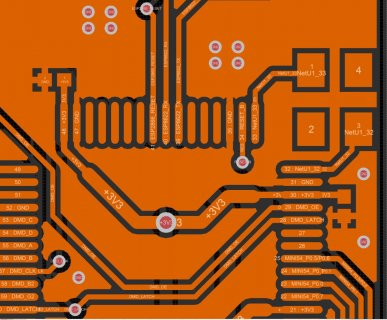
pcb.jpg

Regards
Russell
 
Last edited:
I found this thread which was a very interesting read
https://forum.pjrc.com/threads/33645-Custom-Teensy-Startup-Question/page2

First thing i noticed is every one is using 8pf crystals im using a 10pf but Pauls custom teensy page did say 8-10?

Also the crystal guard ring well looks like iv totally screwd that up as its none existent/ grounds are not even connected. Could this be causing the strange behavior with 2 boards just randomly not running any more?


I had a another project using a stmf4 with a through hole cap and 2 load caps and i remember once i swapped manufacturers on the load cap (same specs just different cheaper manufacturer and all my boards starting dying after few min if operation. So i know how important the crystal circuit is.

I got a feeling my mystery dying boards is related to this Crystal pcb layout not being right.

Regards
Russell
 
I had a another project using a stmf4 with a through hole cap and 2 load caps and i remember once i swapped manufacturers on the load cap (same specs just different cheaper manufacturer and all my boards starting dying after few min if operation. So i know how important the crystal circuit is.

They die ? Do you mean they are broken and do not work anymore ?
A question, are the chips hot ? Did you measure the current ?
 
On the stmf4 project they did not 100% die but started all running wrong frequency and swapping to good components did not recover them. So they where some how damaged.


The two dead custom teensy boards. Are not getting hot 5v goes in the internal reg supplies a very clean 3.3v but my program is no longer running and pc does not recognize the board any more.

So i assume the micro is damaged or Crystal cicruit is no longer running. Just strange how they all work to begin with but die after few days. I must note only 2 out of 25 have died the others so far have being running fine for past 2 months some of them 24/7

Its like something is just on the edge of tolerance or slowly being damaged.

Regards
Russell
 
Oh this is 7.2pf maybe my 10pf is to far out.

I think next steps is switch to using this exact crystal / a 8pf one. And adding this guard ground ring connected only via the gnd plain from with in the mk20

I have read you can change bits in the code to match the pf of your Crystal? Maybe i can bring these dead boards back to life?

Regards
Russell
 
Ah forgot to mention (might be quite important actually) there is a esp8266 module board sat over the crystal. Could its radio waves be upsetting something?

Regards
Russell
 
This is the "old" crystal used on Teensy 3.0 and 3.1.
PJRC switched to another crystal, I think the exact part number was never published, the information we have are: https://forum.pjrc.com/threads/27689-Teensy-LC-Beta-Testing?p=63798&viewfull=1#post63798

Entering the given details in the part search form https://support.epson.biz/td/ps/prod-search.php?id=td_xtal_mhz. From the search results I would select a crystal with 8 or 9pF load capacitance:
8pF https://support.epson.biz/td/ps/productinfo.php?pn=X1E0000210578
9pF https://support.epson.biz/td/ps/productinfo.php?pn=X1E0000210052
9pF https://support.epson.biz/td/ps/productinfo.php?pn=X1E0000210375

The only difference to the one you have selected: the Fo/temp.characteristics tolerance is a bit better (±18ppm vs ±20ppm (your link))
 
Ok cool but the one i selected should be ok?

I can only assume the mixture if 10pf crystal without the gnds connected and no guard ring are causing issues?

Regards
Russell
 
Poor crystal layout usually leads to flaky behavior, but usually not complete death after a period of time.

I'd suggest looking at your input voltage. On Teensy 3.1, the most common failure was death due to overvoltage. Usually USB was fine, but it turns out many switching power supplies create a brief overvoltage spike. You can also get such spikes if using a long wire or series inductor and the current is suddenly interrupted, like turning off the power with a physical switch. These problems are the main reason I replaced the old design with Teensy 3.2. The external regulator with 10V rating is much more robust when abused.
 
My board is powered externally via a 5v 10a laptop style power pack.

What are the signs of an over powered mk20? These ones the regular still works fine and the chip does not get hot. Just does not execute its program any more.

Are you thinking my crystal is good enough to not be the issue and i am looking in the wrong direction?


Thinking i might move my mk20 behind a 5v to 3.3v reg and power the mk20 3.3v directly and by pass its own internal regulator. This with the crystal changes should hopefully bullet proof my design a bit better. I have a feeling its good enough to work but might be a bit fragile?
 
Last edited:
Here is my crystal pcb update
1) grounded the crystal gnd pads
2) added in gnd guard ring only connected via pour from inside mk20

I will use the exact teensy crystal in production runs.
I will also place the mk20 behind a 3.3v reg just like the teensy 3.2 and not bother with the internal reg.
Hopefully these changes will bullet proof my design a bit better :)


pcb1.png

Regards
Russell
 
Yes, that looks good.

But I suspect the regulator is the real issue here. If using one that's rated for 6V max, be sure to put some over-voltage protection parts on your design, if you have room on the PCB. You can always later decide not to populate those parts if they're not needed.
 
Im starting to suspect this as well. I did take one of my 5v 10amp power packs and hook up to a scope and switch on /off multiple times and could not get any spikes out if it. But conditions might change.

I have added in the same reg you use now lp38691sd-3.3 and a 3.6v zener on output to remove any spikes that get through the reg.

Few questions :)
1) You use 2.2uf caps on the reg but datasheet show 1uf or is this just a minimum?
2) Should i have a 6v zener on input of the reg rather then a 3.6v on output? (input voltage from psu is 5.5v) Or does it not matter long as its there. I assume the reg will survive any little spikes?
3) its correct to just leave the mk20 vreg in disconnect and the mk20 regout to 3.3v rail (ie like in your 3.2 schematic)

Regards
Russell
 
Last edited:
Status
Not open for further replies.
Back
Top