Hi All,
I have a problem that I am trying to troubleshoot.
My project calls for listening to RS422 packets from a pre-existing device on my Teensy 3.2, so I have the Sparkfun RS485 breakout (https://www.sparkfun.com/products/10124), and this works for me fine.
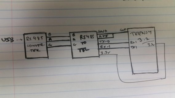
But I want to emulate the RS422 packets for ease of programming. So I have the Sparkfun USB to RS485 converter (https://www.sparkfun.com/products/9822), and I have a terminal on my computer imitating the packets and sending them to the Teensy (via the USB to rs485 converter to the RS485 to TTL breakout). It may seem a little absurd, as I could just use the USB serial instead of this unnecessary conversion. But I want to hot swap my prototype between the two situations. And I also want to emulate the hardware serial limitations and program flow.
But there is something with my configuration that causes the Teensy to stop receiving bytes after the first few, or not receive any.
I don't think there is anything wrong with the Arduino code or the TTL converter config. But I must not have correctly interfaced the USB to RS485. The connections are straightforward (see attached)
I'm using CoolTerm on my mac, and the terminal allows me change RTS, CTS, DTR etc. I'm not sure if it is something to do with that, I've done a fair bit of trial and error there.
I can send a hex string of EE EE EE, and the teensy will reply via USB serial that it has received EE EE EE and a 0, if I send any less or more bytes it doesn't work, and then I can't go back to sending three bytes. If I reboot Teensy it will go back and be able to do the same. This would suggest a code problem, but testing shows it isn't. The RS485 breakout is powered from Teensy and I think the reboot resets it. But none of it makes sense really, It's just so weird!
If anyone has any leads or suggestions that would be much appreciated!
The code is so basic, straight from an example, and works in my other HW serial setup. I'm quite confident there is no errors, but I've attached regardless.
void setup() {
// put your setup code here, to run once:
Serial.begin(9600);
Serial1.begin(9600);
while(!Serial.dtr());
Serial.println("Ready");
}
void loop() {
// put your main code here, to run repeatedly:
int incomingByte;
if(Serial1.available() > 0) {
incomingByte = Serial1.read();
Serial.print("UART received: ");
Serial.println(incomingByte, HEX);
}
}


